Transformer Tap rule

Strathead

Senior Member
Location
Ocala, Florida, USA
Occupation
Electrician/Estimator/Project Manager/Superintendent
I am sure I am going to feel really stupid when someone explains the simple explanation of this question:
So, 240.21 (C)(6) says:

Where the length of secondary conductor does not exceed
7.5 m (25 ft) and complies with all of the following:
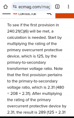
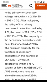
(1) The secondary conductors shall have an ampacity that is
not less than the value of the primary-to-secondary volt‐
age ratio multiplied by one-third of the rating of the over‐
current device protecting the primary of the transformer.
(2) The secondary conductors terminate in a single circuit
breaker or set of fuses that limit the load current to not
more than the conductor ampacity that is permitted by
310.15.
(3) The secondary conductors are protected from physical
damage by being enclosed in an approved raceway or by
other approved means.

I can't understand what they mean by (1) above. I believe the transformer voltage ratio would be 480 to 120 or 4-1 or 4(not to 208 correct?) But I don't see what that has to do with the next part. Say I have a 30 KVA 480 delta to 208/120 Wye transformer with a primary circuit breaker of 40A. 1/3 of that is 13.333 times 4 is 53 amps. So my SECONDARY conductors must have an ampacity of at least 53 amps. Is that all this is saying? That makes no sense to me. What am I missing?
 

wwhitney

Senior Member
Location
Berkeley, CA
Occupation
Retired
I can't understand what they mean by (1) above. I believe the transformer voltage ratio would be 480 to 120 or 4-1 or 4(not to 208 correct?)
That's an excellent question. Do you use the turns ratio of each coil, or do you just take the ratio of L-L voltages? As written, it would be the latter, but I wonder if the former isn't more appropriate. For a 480V : 208Y/120V Delta-Wye transformer, the turns ratio would be 4, but the voltage ratio would be 4/sqrt(3).

But I don't see what that has to do with the next part. Say I have a 30 KVA 480 delta to 208/120 Wye transformer with a primary circuit breaker of 40A. 1/3 of that is 13.333 times 4 is 53 amps. So my SECONDARY conductors must have an ampacity of at least 53 amps. Is that all this is saying?
Yes, subject to the previous question. This 1/3 factor is same as in 240.21(B)(2), the usual 25' tap rule.

Cheers, Wayne
 

Strathead

Senior Member
Location
Ocala, Florida, USA
Occupation
Electrician/Estimator/Project Manager/Superintendent
That's an excellent question. Do you use the turns ratio of each coil, or do you just take the ratio of L-L voltages? As written, it would be the latter, but I wonder if the former isn't more appropriate. For a 480V : 208Y/120V Delta-Wye transformer, the turns ratio would be 4, but the voltage ratio would be 4/sqrt(3).
FYI, in my opinion the voltage ratio is still 480 to 120. Because each coil is actually a transformer and the configuration of them creates the 208.
 

wwhitney

Senior Member
Location
Berkeley, CA
Occupation
Retired
FYI, in my opinion the voltage ratio is still 480 to 120. Because each coil is actually a transformer and the configuration of them creates the 208.
Since the current transformation is 4:1, I think I agree that the section should reference a voltage transformation that is 4:1, I'm just not 100% convinced the current language does that sufficiently unambiguously. But you won't go wrong treating it as 4:1.

So you are saying that my math is the correct math for this section?
Yes, that's it.

If you have a 1:1 isolation transformer, then the math just works out identically to 240.21(B)(2). The reason for the 1/3 factor in each case is the same--some limited measure to help ensure that the SC/GF protection from the upstream OCPD will be sufficient for the conductors whose overload protection is located downstream of their source of supply.

Cheers, Wayne
 

Tulsa Electrician

Senior Member
Location
Tulsa
Occupation
Electrician
I always thought it was line to line or 480 and 208
480/208= 2.307*40/3.

Usually used when there is more than one secondary. This way a minimum would be set for part 1
30 KVA, 480 to 208/120

2.307*40= 92.28
92.28/3=30.76

Then go to part 2 and 3
Would be nice to find out for sure if I have been doing wrong for years. Ah man 😭
Who has a book with the ansawer.
 

Tulsa Electrician

Senior Member
Location
Tulsa
Occupation
Electrician
I went and looked up some double check math for this.
Pretty sure you use line to line.
480/208
40 amp breaker/3= 13.333
Wire for 30.76 amp @75v #10
35*(208/480)=15.166
Wire has to have larger number.

Does this look correct?

Remember we're looking for the minimum required.
 

jaggedben

Senior Member
Location
Northern California
Occupation
Solar and Energy Storage Installer
I always thought it was line to line or 480 and 208
480/208= 2.307*40/3.
...
I agree that the code is unclear. But my understanding is the typical 480 delta to 208/120 Wye consists (essentially) of three 4:1 windings. So, for example, if you drew more than 160A unbalanced @120V L-N on the secondary, you'd draw over 40A L-L on one phase of the primary. (And thus trip the breaker if that is your primary OCPD rating.)

The code probably ought to make this clearer. I generally think that electricians ought to be able to understand the code without needing to understand the internals of equipment, but that will be a bit of a tall order in this cae, IMO.
 

Tulsa Electrician

Senior Member
Location
Tulsa
Occupation
Electrician
I agree that the code is unclear. But my understanding is the typical 480 delta to 208/120 Wye consists (essentially) of three 4:1 windings. So, for example, if you drew more than 160A unbalanced @120V L-N on the secondary, you'd draw over 40A L-L on one phase of the primary. (And thus trip the breaker if that is your primary OCPD rating.)

The code probably ought to make this clearer
. I generally think that electricians ought to be able to understand the code without needing to understand the internals of equipment, but that will be a bit of a tall order in this cae, IMO.
Agree why not stick with 1/3 of secondary current.
It works out close to the same. Unless you use 480/120 in the op question. He came up with 53 amps.
1/3 of the secondary for the 30 KVA
Would be 27.75 amps.
I feel this is where the correct ratio comes in.

I'm just there yet on the 480/120 ratio of 4 for the equation in the example op posted.

I need to find an example of the equation. Work for tomorrow.

Thanks
 

Carultch

Senior Member
Location
Massachusetts
I agree that the code is unclear. But my understanding is the typical 480 delta to 208/120 Wye consists (essentially) of three 4:1 windings. So, for example, if you drew more than 160A unbalanced @120V L-N on the secondary, you'd draw over 40A L-L on one phase of the primary. (And thus trip the breaker if that is your primary OCPD rating.)

The code probably ought to make this clearer. I generally think that electricians ought to be able to understand the code without needing to understand the internals of equipment, but that will be a bit of a tall order in this cae, IMO.

The topology details of the transformer are irrelevant to the calculation. A 480V to 208V wye transformer would be treated the same way as a 480V delta to 120/208V wye transformer, as far as 240.21(C) is concerned. It is the protection of the field-installed wires that concerns 240.21(C). The current inside the windings is out of the picture of what the electrician has to consider.

The time when topology is relevant to 240.21(C), is when qualifying topologies (delta:delta 3-wire, and single phase 2-wire to 2-wire) are exempt from requiring secondary protection. Since overloads will line up winding-to-winding, and not get redistributed on qualifying topologies, the primary OCPD is allowed to indirectly protect the secondary, at a rating that scales by the voltage ratio like a gear ratio. The non-qualifying topologies (those involving wyes & centertaps) introduce the possibility that overload on an individual phase conductor is in the blindspot of the primary OCPD. So these non-qualifying topologies require a secondary OCPD.
 

wwhitney

Senior Member
Location
Berkeley, CA
Occupation
Retired
The topology details of the transformer are irrelevant to the calculation. A 480V to 208V wye transformer would be treated the same way as a 480V delta to 120/208V wye transformer, as far as 240.21(C) is concerned.
Let's leave aside for the moment whether that's true for the language currently used in 240.21(C) and just consider what it should say.

Then I don't see why the above should be true. Clearly the 1/3 factor in 240.21(C)(6) has to do with ensuring that the damage curve for the secondary conductors without overload protection is not too far from the reflected protection curve provided from the primary OCPD. So the ratio we want to use is the ratio of currents that can occur.

With a 480Y/277V to 208Y/120V transformer, a 100A secondary L-N load will draw 100A * 120V/277V = 43.3A through one of the poles of primary OCPD. While with a 480D to 208Y/120V transformer, a 100A secondary L-N load will draw 100A * 120V / 480V = 25A through two of the poles of the primary OCPD. So the ratio used for applying 240.21(C)(6) should differ in the two cases.

Cheers, Wayne
 

Carultch

Senior Member
Location
Massachusetts
With a 480Y/277V to 208Y/120V transformer, a 100A secondary L-N load will draw 100A * 120V/277V = 43.3A through one of the poles of primary OCPD. While with a 480D to 208Y/120V transformer, a 100A secondary L-N load will draw 100A * 120V / 480V = 25A through two of the poles of the primary OCPD. So the ratio used for applying 240.21(C)(6) should differ in the two cases.

I don't agree with this calculation. 100A at 120/208V is 36 kVA. Assuming 100% efficiency, this means that 36 kVA should also be drawn from the primary breaker.

A 3-phase circuit with a 480V interphase voltage, delivering 36 kVA will draw 43.3A. Drawing only 25A on the primary, just because a delta primary is used, would mean the transformer would have to create energy, for the secondary loads to draw 100A.

Sure, the current inside the primary windings will only be 25A for the delta primary of this transformer, but the current of adjacent primary windings will still add up as vectors to draw 43.3A from each primary phase conductor.

This is why this section calls out the voltage ratio, rather than the turns ratio. The voltage ratio is the turns ratio, for same primary & secondary topologies. For mixed topology transformers, there's vector math required to convert a turns ratio into a voltage ratio.
 

Tulsa Electrician

Senior Member
Location
Tulsa
Occupation
Electrician

Attachments

  • Screenshot_20231215-224322.png
    Screenshot_20231215-224322.png
    199 KB · Views: 6
  • Screenshot_20231215-224430.png
    Screenshot_20231215-224430.png
    177.5 KB · Views: 6

Strathead

Senior Member
Location
Ocala, Florida, USA
Occupation
Electrician/Estimator/Project Manager/Superintendent
Found what I was looking for.
Ecm mag and Mike holt video.
If I understood the question. I stand by my equation.
The only thing. Mike holt video used 1/3 of secondary current rating of the transformer.
Link to the artical https://www.ecmag.com/magazine/articles/article-detail/codes-standards-sizing-conductors-part-xxxvi

An example in the chapter 9 would help clear things up.

I could not wait untill tomorrow would not be able to sleep.
I, for one, consider that settled. I can’t remember when I have used a power and lighting transformer where the secondary OCP was less than the transformer rating, so for practical application the 25 foot rule is generally acceptable. That was really my concern.
 

Carultch

Senior Member
Location
Massachusetts
I, for one, consider that settled. I can’t remember when I have used a power and lighting transformer where the secondary OCP was less than the transformer rating, so for practical application the 25 foot rule is generally acceptable. That was really my concern.
Right. 9 times out of 10, if you are fully utilizing the transformer kVA on the circuit in question or close to it, either the 10 ft rule or 25 ft rule is good to go, and as long as you use at least as much ampacity as your secondary OCPD.

Where you likely may see the one-tenth or one-third part of this rule govern a wire size, is if one transformer feeds multiple secondary circuits, where one circuit by default would otherwise just have a quarter the ampacity of the secondary amps corresponding to the KVA rating.
 

wwhitney

Senior Member
Location
Berkeley, CA
Occupation
Retired
I don't agree with this calculation. 100A at 120/208V is 36 kVA. Assuming 100% efficiency, this means that 36 kVA should also be drawn from the primary breaker.
No, you are misconstruing my calculation. I am not considering the balanced case, as I expect the unbalanced case will be worse. 100A @ 120V = 12 kVA. 25A @ 480V = 12 kVA. As expected.

So if on the secondary side, one ungrounded conductor shorts to ground/neutral, then the reflected current on two of the primary ungrounded conductors will be 1/4 of the fault current through the ungrounded secondary conductor. Therefore if you are considering how the primary OCPD protects that secondary conductor, we should take the primary OCPD's trip curve and multiply the current scale by a factor of 4.

Thus theory-wise, for parity with 240.21(B)(2), the correct ratio to use in this case is 480/120 = 4, not 480/208. Obviously the current text in 240.21(C)(6) is easily read to mean 480/208, not 480/120. This ambiguity is a flaw in the text.

Cheers, Wayne
 

Carultch

Senior Member
Location
Massachusetts
No, you are misconstruing my calculation. I am not considering the balanced case, as I expect the unbalanced case will be worse. 100A @ 120V = 12 kVA. 25A @ 480V = 12 kVA. As expected.

So if on the secondary side, one ungrounded conductor shorts to ground/neutral, then the reflected current on two of the primary ungrounded conductors will be 1/4 of the fault current through the ungrounded secondary conductor. Therefore if you are considering how the primary OCPD protects that secondary conductor, we should take the primary OCPD's trip curve and multiply the current scale by a factor of 4.

Ok, now I understand what you mean. And this is why secondary OCPDs are required for mixed topology transformers, while only the qualifying topologies allow the primary indirectly protect the secondary. The code still tells us to use the voltage ratio of the transformer, rather than the voltage ratio of an individual pair of windings.

The way I understand it, is that the secondary OCPD will protect against moderate degrees of overload, since the cause of a moderate degree of overload, will ultimately be load-side of the secondary OCPD anyway. An overcurrent due to a short circuit, will draw significantly greater overcurrent, that will still be shut off by the primary OCPD, even with the transformer rearranging the currents to multiple phases.

Since the secondary conductors are only protected in excess of their ampacity, the length limitations are there for circuits in a building, so that the length of the not-yet-protected conductors is kept within reasonable limits to reduce the risk of faults.
 

wwhitney

Senior Member
Location
Berkeley, CA
Occupation
Retired
The code still tells us to use the voltage ratio of the transformer, rather than the voltage ratio of an individual pair of windings.
I disagree that the language is unambiguous in this regard, and given the physics, the correct way to interpret the language is as the latter.

For a simpler version of the OP's question, consider a 240V : 120/240V single phase transformer. Should the voltage ratio be 240/240 = 1, or 240/120 = 2? Should 240.21(C)(6) end up treating the secondary conductors exactly the same as tap conductors under 240.21(B)(2), or should the threshold minimum ampacity be higher because of the possibly higher current transformation ratio?

Cheers, Wayne
 

Tulsa Electrician

Senior Member
Location
Tulsa
Occupation
Electrician
For me I had a concern applying the ratio multiplayer due to the with stand rating of the secondary conductor and primary OCPD in a fault situation.

I was thinking that I was applying.and not calculating the primary correctly which could damage the secondary conductors during a fault. So I was a little worried.

I will give an example of the math I use to see if it's correct. I would hate to find out I was teaching wrong. If so I need to correct it.

Based on my math:
I would use a #10 then at 76c
If I take it at 1 cycle the published (ICEA) withstand rating would be 4,300.

This would be put on the primary at the voltage ratio. Then the the primary OCPD would need to open prior to exceeding the withstand rating of the secondary conductor.

Examples:
4300*(208/480)=1863
4300*(120/480)=1075

Now if the ratio of 4 was used.
The minimum secondary conductor. Would be listed from OP, 53 amps. Then a #8 at 75c would apply and the withstand rating changes.

The #8 from same with stand chart would be 6,800.

Examples:
6800*(208/480)= 2946
6800*(120/480)= 1700

Based on these examples you can see even with the larger wire there could be insulation damage if the in correct ratio was used selecting the primary OCPD.

I am not bringing transform impedance into this for a base value.

Granted this is all hypothetical.
So I agree it would be good to clear this up.

Pointing out the important of the ratio and it's effect on the primary to protect the secondary conductors.

Hopefully you see why I was concerned. What I got from Mike holts video was since he just dismissed the ratio and focused on the 1/3 it not a big deal.

In reality it only comes into play with multiple secondary. So it does have merit.

Commentary;
Sometimes we forget how fault current comes into play untill we look for the why it got damaged. So the I feel the NEC said let's make it simple to follow with out all the math. Me for one I'm not an engineer so why do I need to know I only install not design. With that being said I will not value engineer my self into a failure.

So the correct ratio matters to be NEC compliant in that math.
Now for the OCPD fault current limiting aspect. I see nothing other than over current protection and the trip curves of the OCPD set by other. This is where I hand it off to a professional engineer to design.

If they say #8 and only need #10 based on the ratio per NEC I'm not going to argue, #8 it is. If the inverse was true I would look closer based on what I know looking for red flags following the steps.

This may not a 30 KVA it may be 112.5 and larger. So yes I feel it matters.

Thanks for asking the question and others comments. Learning is fun. The education is most helpful.

Tulsa
 

wwhitney

Senior Member
Location
Berkeley, CA
Occupation
Retired
Do you use the turns ratio of each coil, or do you just take the ratio of L-L voltages? As written, it would be the latter
I'm going to withdraw that last sentence above. Looking at the 240.21 language more closely, it just says "primary-to-secondary voltage ratio." Where there are multiple non-zero primary or secondary voltages, this phrase does not specify which primary-to-secondary voltage ratio to use.

Based on the context and all the above discussion, I think the intention is to use the primary-to-secondary voltage ratio that corresponds to the maximum current transformation ratio. I would like to make a future PI that clarifies this, but it looks to be tricky to do so when stated in terms of voltages.

Cheers, Wayne
 
Top