Troubleshoot

Status
Not open for further replies.
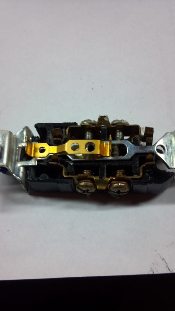
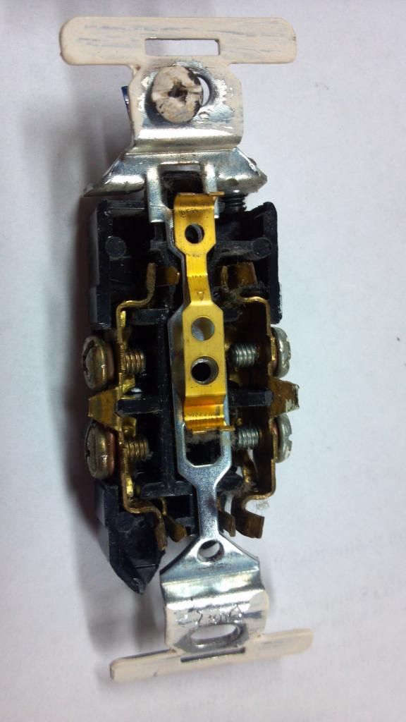
Here are a couple of pics of the receptacle I took apart.

I hope they are good enough to see that nothing the plate screw can contact would bridge the two halves on this particular receptacle.

As I said earlier, the brass piece that sits on top that is for the grounding pin is the closest thing but it is too short. It or the screw touching the hot prongs would be a dead short.

I honestly don't know what the case is with the OP's receptacles.


I just want to say that I relayed the info as best as I could. I did not make any of it up and after being reminded that the center screw would be grounded through the yoke...I am also somewhat baffled as to how the problem existed/was resolved.

In hindsight, I apologize for the guessing part at the beginning of this thread because never in a million years would anyone have ever guessed the long cover plate screw, since it seems impossible to have been the problem/solution.
 
When did you shprt out the circuit

When did you shprt out the circuit

If the red and black had a were shorting together, and you shorted out the circuit it may have blown the original short clear.
 
The 'black' and 'red' are electrically connected or 1/2 of each receptacle will not work.


exactly.

when the switch is off, 1/2 of each receptacle was not supposed to be live. but it was.


2 wire line to switchbox.
3 wire load from switchbox.

bare EGC's wire nutted together
white grounded conductors wire nutted together
blackfrom 2 wire feed and black from 3 wire are wire nutted together and pigtailed to one screw of the switch
red from 3 wire on other screw


3 wire goes to rec#1 then rec# 2 then rec#3


EGC in all 3 rec boxes are properly connected and terminated.

white grounded conductors are properly connected in all 3 rec boxes and pigtailed to each receptacle.

black constant hot wires are properly connected in all 3 rec boxes and pigtailed to the bottom half of each receptacle (the tabs are properly broken).

red switched wires are properly connected in all 3 rec boxes and connected to the top half of each receptacle.

Sorry I didn't break the wiring schematic down previously. I foolishly assumed readers would believe me when I said the circuit was correctly wired.
 
exactly.

Sorry I didn't break the wiring schematic down previously. I foolishly assumed readers would believe me when I said the circuit was correctly wired.

I don't think I ever said I thought you had it wired wrong. If I did, I didn't mean to!:happyno:

Also, the pics I posted wasn't to show you up or say I didn't believe you. If they came off that way I apologize. I was mainly doing it for my own curiosity and to give you and others a view of the inside of the particular receptacle that I had, and maybe for you or someone else to see what could have caused the problem.

I've had stranger things happen and I know it bugs me when I don't know for sure what corrected the problem. But sometimes due to time (money) you just have to move on and think on it later.


No Little Bill, I wasn't thinking of you or your posts at all. You "saved" me from cutting a receptacle in half:thumbsup:. TY.
 
Status
Not open for further replies.
Top