VFD Long Lead Lengths - Correctly Calculating Voltage Drop

Status
Not open for further replies.

iwire

Moderator
Staff member
Location
Massachusetts
iwire, you claimed Bes to be a VFD expert.

Let the expert explain the VFD voltage drop phenomenon with his own examples to the ordinary engineers.:)

Just what I thought, you cannot do it.

That's OK, I can't either that is why I listen instead of trying to fake it. :D
 

Besoeker

Senior Member
Location
UK
iwire, you claimed Bes to be a VFD expert.

Let the expert explain the VFD voltage drop phenomenon with his own examples to the ordinary engineers.:)
The ordinary engineer who claims that the input current to the VSD is more sinusoidal than the output?

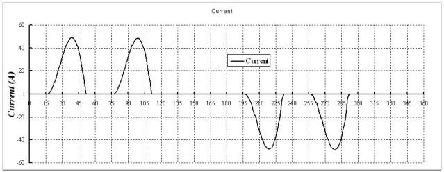
Typical input current:

Idiscontinuous_zps1dc92984.jpg
 

Besoeker

Senior Member
Location
UK
For completion, show it also please.
You want me to present detailed contract information on a public forum?
I've already given you sufficient information, perhaps more than I strictly should have about a customer and an installation.
If you doubt its veracity that's your problem, not mine.
 

Sahib

Senior Member
Location
India
The OP's problem appears to be more of a surge of reflected voltage wave than of a voltage drop. Maximum length of VFD output cable is usually specified by the VFD manufacturer to limit the voltage surge and keep the voltage drop within 3%. If the cable length is more, power conditioning equipment may be installed.

It is not clear why OP did not consult with the manufacturer of the VFD in the first place.
 

Besoeker

Senior Member
Location
UK
The OP's problem appears to be more of a surge of reflected voltage wave than of a voltage drop. Maximum length of VFD output cable is usually specified by the VFD manufacturer to limit the voltage surge and keep the voltage drop within 3%. If the cable length is more, power conditioning equipment may be installed.

It is not clear why OP did not consult with the manufacturer of the VFD in the first place.

Clearly, VFDs are not your forte.
When you are in a hole........
 

Besoeker

Senior Member
Location
UK
Still you are not clarifying.

Once more, do not play games, Bes.
OK.
Post #43 for input current.
Output current is a close approximation to a sine wave.
BS7671 gives volt drop in mV/A/m.

What more do you want/need?
 

winnie

Senior Member
Location
Springfield, MA, USA
Occupation
Electric motor research
I am pretty sure that the OP understands the issue of dV/dt and reflected waves, and is specifically asking about ways in which the voltage drop between VFD and motor would be much greater than expected.

A pissing match about the harmonic content of the drive output doesn't answer the question.

Now, describing what sort of inverter has a high harmonic output might help the OP, because they might say 'oh....this inverter is one that does have a high harmonic output and thus significant harmonic voltage drop'.

A common DC voltage link PWM output inverter will have a fairly sinusoidal output current with ripple at the switching frequency; I believe that an ordinary voltage drop calculation at the drive output frequency (60Hz in this case) is sufficient.

Unless: could capacitive coupling of PWM switching to ground cause a large voltage drop over such a long circuit? This wouldn't be inductive voltage drop; but it would be reactive...

-Jon
 

LMAO

Senior Member
Location
Texas
..... match ain't over until I say so.

VFD Input (line):
Voltage: about 5 to 10% harmonic depending on several factors
Current: +10% harmonics depending on several factors

VFD output (load):
Voltage: PWM (little resemblance to sinewave)
Current: relatively clean sinewave
 

Besoeker

Senior Member
Location
UK
I am pretty sure that the OP understands the issue of dV/dt and reflected waves, and is specifically asking about ways in which the voltage drop between VFD and motor would be much greater than expected.

A pissing match about the harmonic content of the drive output doesn't answer the question.

-Jon
It wasn't a p1ssing match. Just an attempt to clarify harmonic issues that some seem to wish to conflate with the fundamental.
 

Sahib

Senior Member
Location
India
I am pretty sure that the OP understands the issue of dV/dt and reflected waves, and is specifically asking about ways in which the voltage drop between VFD and motor would be much greater than expected
The impedance of VFD output cableshould be matched to that of motor to avoid reflected voltage wave. The impedance and also voltage drop depends on length of cable. Naturally drive manufacturer recommending maximum cable length for their drive to avoid voltage wave reflection should have also considered prospective voltage drop in cable(to keep it within 3%). That is why I asked whether OP consulted with drive manufacturer.
 

iwire

Moderator
Staff member
Location
Massachusetts
. Maximum length of VFD output cable is usually specified by the VFD manufacturer to limit the voltage surge and keep the voltage drop within 3%.

I doubt the max recommend length has anything at all to do with voltage drop. Voltage drop can be overcome by the wire size.
 

Besoeker

Senior Member
Location
UK
The impedance of VFD output cableshould be matched to that of motor to avoid reflected voltage wave.
I feel sure that your immense and vast practical experience in this field is invaluable and plumbs the great depth of the topic.
 

LMAO

Senior Member
Location
Texas
The impedance of VFD output cableshould be matched to that of motor to avoid reflected voltage wave. The impedance and also voltage drop depends on length of cable. Naturally drive manufacturer recommending maximum cable length for their drive to avoid voltage wave reflection should have also considered prospective voltage drop in cable(to keep it within 3%). That is why I asked whether OP consulted with drive manufacturer.
.......

I've been in the VFD industry for 20 years and understand the problems associated with dv/dt and long lead lengths. So please do not discuss the effect peak voltage has on the motor or best practice in motor lead length. I'd like this discussion to be very specific to voltage drop at the motor.
 

smoothops10

Member
Location
FL
Occupation
EE
I doubt the max recommend length has anything at all to do with voltage drop. Voltage drop can be overcome by the wire size.

Somewhat true. The resistive loss can as R=pl/A so as A goes up the R goes down. However, I believe it can be shown mathematically that an ideal conductor has the inductance of L=0.5*10-7 H/m. Note there is no variable term in that equation. The inductance and thus inductive reactance stays the same independent of the size of the wire. So you could approximate the inductive reactance of the wire at 2piFL * 1000m = 0.1885 ohms/km for any size. This is evident in Chapter 9 Table 9. Look at the first column for inductive reactance Xl. It goes from 0.19ohms/km for #14 to 0.121ohms/km for 1000kcmil. Xl reduced by not even a factor of 2. Whereas the resistance goes from 10.2ohms/km to .151ohms/km. Almost a factor of 70. Larger wire will reduce the resistive losses. But additional sets may be required to reduce the inductive losses.
 

Sahib

Senior Member
Location
India
Well, a straight forward answer is voltage drop is dependent on the cable impedance (R+jX) and its length.
I would follow normal approach in voltage drop calculation for your application.
Mike holt free resources have a good Voltage drop tool. Check it out. http://www.mikeholt.com/freestuff-menu.php

It is not that easy: cable impedance depends on harmonic current from VFD.

A similar thought was expressed by weressl in this thread:

http://forums.mikeholt.com/showthread.php?t=123127
 

Besoeker

Senior Member
Location
UK
It is not that easy: cable impedance depends on harmonic current from VFD.
Which is usually insignificant.
I suggest you measure on one of your installations.
I may give yor post the merit it deserves after I have walked the first couple of miles with our black and white handsome beast.

IMG_1917_zpssy8ys0rw.jpg
 
Last edited:
Status
Not open for further replies.
Top