VFD Long Lead Lengths - Correctly Calculating Voltage Drop

Status
Not open for further replies.

mike_kilroy

Senior Member
Location
United States
... There is a TCI dv/dt filer in the motor circuit as well.

Perhaps his Xl voltage drop addition is not due to the cable, but due to this series inductor? What is the model/specs on the TCI "filter?" The are often speced as "X% impedance;" which is really X% voltage drop at rated current flow.

I have seen no indication of including this voltage drop in your OP, and it certainly may be a significant portion - depending on the filter design.
 

Ingenieur

Senior Member
Location
Earth
Assume 6 pulse drive
pu current FFT (typical and for calculation reference only) ABB VFD
freq/harm...pu
f 0.6
5 0.20
7 0.14
11 0.09
13 0.07
17 0.06
19 0.05

X = L/2 x 2 x D/1000 x 2 x Pi x 60 x (0.6x1 + 0.2x5 + 0.14x7 + 0.09x11 + 0.07x13 x 0.06x17 + 0.05x19)
= 0.377 L D (6.45) = 2.43 L D
this tells us harmonics increase X by 645% over a fund only

L = 3 ph inductance for 1 set, we have 2) 4/0 per 1000' calculated from NEC table steel cnd
= 135 uH = 135 x 10^-6
D = distance 2200'

X = 2.43 x 2200 x 135 x 10^-6 = 0.72 Ohm
R is easily calculated 2 x 2200/1000 x 0.063/2 = 0.14 (26 vdrop at 190 A)
Z = sqrt(R^2 + X^2) = 1.1 ohm

will be much lower for a 12 (or 18) pulse since fund 0.8+ (0.9+) and harmonic sum
muh lower but of higher freq

I figure the op's engineer did something like this for his calc
 
Last edited:

Besoeker

Senior Member
Location
UK
That is lame. The VFD output has harmonics with 5th and 7th predominant. If you do not agree, please show with your own meaurement from field.
Thank you once again for your kind, informative, and erudite response.
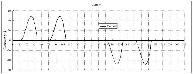
With your keen powers of observation you will have noted that the magnitudes given are the exact reciprocal of the harmonic number. That would require the input current to be a rectangular 120deg wave. Exactly level DC out of the bridge. This would be approximately true on a DC dive. Not really very likely on a variable frequency drive unless it has an approximately infinite DC choke and many of the cheap and nasty ones don't have any DC choke at all. So you get discontinuous current pulses.

Idiscontinuous_zps1dc92984.jpg


Fifth is often quoted as 40% or more.
 

winnie

Senior Member
Location
Springfield, MA, USA
Occupation
Electric motor research
Assume 6 pulse drive
pu current FFT (typical and for calculation reference only) ABB VFD
freq/harm...pu
f 0.6
5 0.20
7 0.14
11 0.09
13 0.07
17 0.06
19 0.05

Those numbers are suggestive of a 'current source inverter', where the DC link between rectifier and output switches is a large DC inductor rather than a capacitor bank.

In a CSI the inductor acts to maintain constant current through the switching elements and the load. A six step CSI will have output _current_ pulses that are approximately 120 degree square pulses with huge harmonic content.

Beo can comment about how likely it would be to find a six step CSI on a low voltage 200 hp drive installed in the past couple of years. I was under the impression that they were used at higher voltages, and are an older technology.

IMHO it is very unlikely that the drive that the OP is dealing with is a CSI, and unlikely that the OP is dealing with such high harmonic current. However the calculation showing the high voltage drop associated with such an inverter is possibly very useful to the OP because the 'other engineer' might be using the same sort of assumptions to come up with a voltage drop calculation.

-Jon
 

Sahib

Senior Member
Location
India
Bes: Fourier analysis of any VFD output has harmonics with 5th and 7th harmonics predominant to be attenuated by output filter/motor inductance Why not demonstrate it with your own meaurement from field?
 

iwire

Moderator
Staff member
Location
Massachusetts
Bes: Fourier analysis of any VFD output has harmonics with 5th and 7th harmonics predominant to be attenuated by output filter/motor inductance Why not demonstrate it with your own meaurement from field?

How about this, I will ask of you what we ask of all folks here.

You put your own figures up, not a link, your own figures to prove the point you want to make. Before asking others to show you how it is done.
 

Besoeker

Senior Member
Location
UK
Those numbers are suggestive of a 'current source inverter', where the DC link between rectifier and output switches is a large DC inductor rather than a capacitor bank.

In a CSI the inductor acts to maintain constant current through the switching elements and the load. A six step CSI will have output _current_ pulses that are approximately 120 degree square pulses with huge harmonic content.

Beo can comment about how likely it would be to find a six step CSI on a low voltage 200 hp drive installed in the past couple of years. I was under the impression that they were used at higher voltages, and are an older technology.
I have only ever dealt with one and that was probably somewhere around two or possibly even three decades ago.
For drives in the MW range, we had our own design of the Static Kramer.
 

mike_kilroy

Senior Member
Location
United States
I have only ever dealt with one and that was probably somewhere around two or possibly even three decades ago.
For drives in the MW range, we had our own design of the Static Kramer.

Didn't the OP current feedback picture prove it was 6 step? Maybe ya'll need to go look at that cool 6 step sine wave he posted again?

Don't forget the voltage drop on the output LCI inductor!
 

Ingenieur

Senior Member
Location
Earth
Not going to happen.
lol
big difference between selling and applying a converter and designing one
they are used for more than xxx HP motor drives

such as 1 MV DC links and xxx MW pf correction and fault transient control
in these applications the OUTPUT is injected onto the grid
this requires harmonic distortion mitigation
iso transforrmers
tuned LC filters based on the output characteristics
variable switching timing/angles
etc

you never explained what method you think the op's engineer used to arrive at a 15-20% drop
we know the R drop is 3-6% depending of whose calcs you use
 

Attachments

  • image.jpg
    image.jpg
    15.7 KB · Views: 0

winnie

Senior Member
Location
Springfield, MA, USA
Occupation
Electric motor research
Are you saying there is no harmonics in output wave form of VFD PWM drive?

First you must differentiate between voltage harmonics and current harmonics.

A voltage source inverter (the kind with an input rectifier, capacitor filter, and output switches) will have a very ugly waveform at the switching frequency, and will have 'harmonics' associated with that. (Harmonics in quotes because the switching components of the output waveform are generally not harmonic multiples of the desired output frequency.) However the inductance of the motor (and circuit conductors) will act as a much higher impedance to these high frequency components. So the output _current_ of the inverter has much lower 'harmonic content' than the output _voltage_.

There will be _some_ harmonic current in the output of a modern PWM VFD, however below the switching frequency, such harmonics (both voltage and current) will be minimal, certainly not 20% of the fundamental. Below the switching frequency, any harmonic current has to do with imperfections in the PWM generation, and proper design should minimize this. At the switching frequency there is pretty significant current flow, however inductive reactance in the conductors to the motor will act to reduce this switching frequency ripple.

The waveforms in this article match what I've seen on my own research inverters; you can see the huge ugly waveform for a voltage source six step drive.
http://powerelectronics.com/motion-systems/motors-efficiency-and-adjustable-speed-drives

The waveforms in this article match what I've seen for output voltage on inverters:
http://www.inverter.co/inverter-troubleshooting-guide-547067.html

-Jon
 
Status
Not open for further replies.
Top