Why is residential wiring known as single phase?

Status
Not open for further replies.
We used an hp audio oscillator as the reference and a Heathkit scope to check the frequencies of audiometers. This was in the late 50s. Vacuum tube days, or should I say valves?
Thermionic valves maybe?
Solid state devices post dated me by some years. They were around when I started higher education but education takes some years to catch up. Maybe more correctly, it has an inherent lag.
We got lumbered with triodes and pentodes that had their days numbered and were pretty much off the radar by the time I got to work.
I have come across thyratrons and mercury archaic rectifiers. But generally to replace them with solid state. That's mostly where my area of expertise is. Power electronics.

That said, when I first started in the field I worked for a company that had been making variable speed DC drives for decades, mostly for the paper making industry.
These were electro-mechanical. Carbon pile regulators that squeezed a pile of carbon discs together to reduce resistance.
And faceplate regulators that took demanded speed and actual speed into a differential gearbox and moved an arm around a big potentiometer to vary resistance.
In terms of speed holding, these worked extraordinarily well. Even by modern standards.

I digress.
 
120215-1620 EST

T.M.:

Relative to post 832. A transformer with only two secondary wires has only one phase.

If I want to derive something from that then I could have any reasonable number of phases. But in one very typical application I have a two phase motor that is called a "capacitor run single phase motor". The second phase is created from the input single phase with a capacitor.

.
 
These were electro-mechanical. Carbon pile regulators that squeezed a pile of carbon discs together to reduce resistance.
And faceplate regulators that took demanded speed and actual speed into a differential gearbox and moved an arm around a big potentiometer to vary resistance.
In terms of speed holding, these worked extraordinarily well. Even by modern standards.

Bes, have you ever seen rheostats made by lowering metal plates in water? I digress further.
 
Definition of Phase:

Definition of Phase:

Phase: Phase is the fractional part of a period through which time or the associated time angle wt has advanced from an arbitrary reference...........

[Kerchner and Corcoran, Alternating-Current Circuits, Wiley, 1951]
 
Phase: Phase is the fractional part of a period through which time or the associated time angle wt has advanced from an arbitrary reference...........

[Kerchner and Corcoran, Alternating-Current Circuits, Wiley, 1951]
I'll buy that one too.
 
When I connected the probes as you requested in post #747, this is what I got:

X-Ymode.jpg
Why can't you get a graph like below because an oscilloscope in x-y mode can display any Lissajous figure?
 

Attachments

  • Ljfig1.jpg
    Ljfig1.jpg
    2.7 KB · Views: 0
Last edited:
An illustration

An illustration

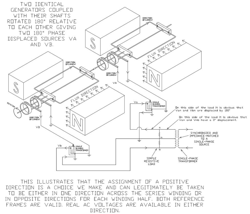
The following graphic will illustrate why I contend that the positive direction is a choice we make and is not a given.

The top left starts with two identical generators with their shafts coupled together and with one generator rotated 180? relative to the other. Both generators are frame grounded so we can't play games with the polarity. This gives us two voltages that are physically displaced by 180?.

As we move to the right, the generated voltages are fed into two single-bushing, tank-grounded transformers (again so we can't play games with the polarity). These secondary voltages then feed a simple two-resistor circuit and are still two 180? displaced voltages.

From the right, we start with a single-phase source. This feeds a center-tapped single-phase transformer that is impedance matched and source-synchronized so we can parallel feed the simple two-resistor load. This is what we all easily recognize as a feed having two in-phase voltages in one direction across the windings: our conventional single-phase source.

So at the load we have voltages that, if seen from the left feed, are displaced by 180? but if seen from the right feed have a 0? displacement. That is why I say the positive direction is a choice and that both voltages exist and map to the same physical space. Both directions are valid and both sets of voltages exist.

180degGen-Circuit-1PTrans.jpg
 
Last edited:
Mivey,
So let's take this one very small step at a time.

Arbitrarily in the order A, N, B and T=360 being one complete cycle.
T= 0; 0,0,0
T= 90; -120, 0, 120
T=180; 0,0,0
T=270; 120, 0, -120

Any problems here? Presuming VAC sinusoidal, arbitrary zero reference based on convenience and popularity, etc. etc.
No problems so far, so carry on. But, please review my graphic that I just posted as it may answer some questions and might save you some typing.
 
Last edited:
The following graphic will illustrate why I content that the positive direction is a choice we make and is not a given.
Has anyone said what direction must be chosen as positive at the exclusion of other choices?

But you do raise the point:
If the positive direction is in opposite directions for each halve, then aren't both halves reaching their maxium positive value at the same time?
Maxium positive value at the same time, zero crossing at the same time - isn't this 'in-phase'?
 
Has anyone said what direction must be chosen as positive at the exclusion of other choices?
There is certainly resistance to saying that two voltages can have a real physical 180? phase displacement when present across two series windings.

But you do raise the point:
If the positive direction is in opposite directions for each halve, then aren't both halves reaching their maxium positive value at the same time?
Maxium positive value at the same time, zero crossing at the same time - isn't this 'in-phase'?
The "maximum positve value" is the sticking point.

Viewed from the right side of my graphic, that reference frame would say that the positive peaks of both waveforms occur in the same direction at the same time. Their negatives work in synch in the opposite direction 180? later.

Viewed from the left side of my graphic, that reference frame says the positive peak of one waveform is working in synch with the negative peak of the second waveform. They also work together in the opposite manner at a point 180? later.

As my graphic shows, the voltages map to the same physical space and the only thing that makes a difference is the reference frame we choose. Both reference frames are valid and both voltage sets actually exist as can be seen by the voltages across the load in my graphic.

In other words, the voltage is relative and there is no universal reference.
 
Phase: Phase is the fractional part of a period through which time or the associated time angle wt has advanced from an arbitrary reference...........

[Kerchner and Corcoran, Alternating-Current Circuits, Wiley, 1951]
How will you measure it?
 
The following graphic will illustrate why I contend that the positive direction is a choice we make and is not a given.
You may have noticed that I have been quite silent in this discussion for several days. That is because no one has made any missteps into saying things like "the windings are out of phase". I believe that issue was cleared up a few days ago.

As I already acknowledged, your example above does demonstrate a situation where the windings are physically out of phase, even though we may choose to view them from different points to make them appear in-phase or out-of-phase. This does reveal the difference in the realities, but does not address the "appearances" that are currently being argued by most posters.

<end comment to Mivey>

I am not exactly sure why I am responding right now, but one thing I have noticed in the last few days is that this discussion has now boiled down to arguing opinions. Those arguments have little merit, regardless which side one wishes to take. For these arguments, both sides are wrong. That's like telling someone they are wrong because they chose to vote for a different politician than another person chose.

Trying to prove that someone else's opinion is wrong is futile, and that is why this discussion is currently going in circles with no coherent direction. It is my personal wish that people stop arguing opinions and focus on more fact-based discussions. Once people accept the fact that someone else chooses a different opinion, then it will become clearer that no one is actually disagreeing with each other.

The arguments are ensuing because each person is so headstrong in their opinion that they are overstating its appearances as fact, and then also dismissing the other side's appearances as non-fact. If everyone would stick to the absolutes and stay away from the opinions, this would actually be resolved very quickly.
 
Why can't you get a graph like below because an oscilloscope in x-y mode can display any Lissajous figure?
It was in XY mode as you can clearly see, connected as you required it to be per post #747, and it is displaying a Lissajous figure.
Showing precisely what one would expect it to show.
And indeed, that which you ought to have been able to predict in accordance with your verbose description in post #824.
 
It was in XY mode as you can clearly see, connected as you required it to be per post #747, and it is displaying a Lissajous figure.
Showing precisely what one would expect it to show.
But see this
First you please check the continuity between the grounds of two probes connected to the scope in the X-Y mode.Does the continuity exist?

Have you done it?What is the result?
 
But see this


Have you done it?What is the result?
I have no need to do that. See post #232. And several others.

I gave you the XY plot that does nothing more that does nothing more than confirm the YT plot I posted in #404.
Surely you really didn't expect it to show anything other than that?
 
I have no need to do that.

But does the test,you have just done with your own scope,proves to you that if a sinusoidal quantity V*sin(wt+180) i.e -V*sin(wt) exists,its opposite V*sin(wt) can also exist?
 
But does the test,you have just done with your own scope,proves to you that if a sinusoidal quantity V*sin(wt+180) i.e -V*sin(wt) exists,its opposite V*sin(wt) can also exist?
No.
What shows is that Van and Vbn are mutually displaced by 180deg.
If you take a single supply of just 120V it is just a single supply of 120V, Reversing how you measure it doesn't reverse its phasing.
That would be like saying a 1.5V battery ahs two different voltages. Clearly, that's nonsensical.
 
Status
Not open for further replies.
Top