Yes. It was supposed to be:
the fact that the X1->X2 voltage is in phase with the X3->X4 voltage and the fact that the X1->X2 voltage is opposite in phase to the X4->X3 voltage.
Never said you need to change the transfromer to go from Vnb to Vbn,
Well me neither so why is it a topic? One of my arguments is that both voltages exist in the normal fixed-configuration center-tapped transformer.
I guess I missed where I said two independent sources could not be interconnected/ Oh yeah, I have been focusing only on the transformer connections used in millions of installations.
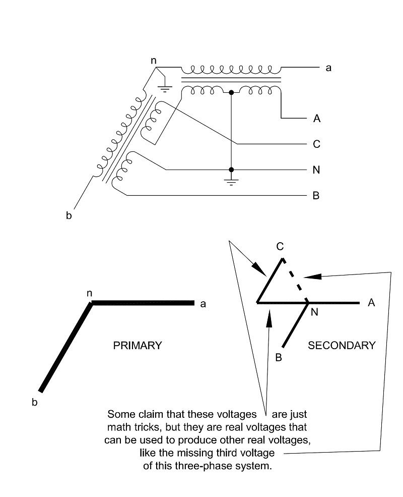
Great so we see the transformer on the right is what we are all familiar with: a single-phase center-tap fed by a single-phase source. One side has said the voltages are in phase. Well that is true for the X1->X2 voltage and the X3->X4 voltage. That is a 0? difference going end-to-end across the windings. We have also referred to this as Van and Vnb having a 0? phase difference: Van in phase with Vnb.
But some have denied there are also voltages in those windings that are not in phase. The purpose for the 2-generator source coming from the left is to show that the X2->X1 voltage and the X3->X4 voltages are not in phase. That is a 180? difference going from end-to-neutral across the windings. We have also referred to this as Van and Vbn having a 180? phase difference: Van phase-opposed to Vbn.
Some have claimed you can't have both voltages and there is only one reality. My graphic illustrates that you can indeed have both and the difference is the reference frame ("end-to-end" vs "end-to-neutral").
Both cases are reality and no physics are violated for both voltage sets to physically exist at the center-tap secondary. That was the purpose of paralleling the two sources across the load. Nothing blows up, no physics are violated, both sets of real voltages exist.
The physics defining the voltage directions on the left and the physics defining the voltage directions on the right use the same rules and yet we wind up with both in-phase and phase-opposed voltages sharing the same space. So "the physics" do not result in only one reality. The reality is that the positive voltage direction is a choice we make and either direction is valid. Nothing about the physics says we have to use one linear direction across both series windings as the positive direction.
You are the one who chooses a voltage directions, so I thought it interesting you would show that the voltage across and the current through a resistive load are not consistent.
I don't see your point. I have not made such a claim. The waveforms are bi-directional and current changes direction every 1/2 cycle. I believe it is the default assignment of a positive direction that is making you think there is an inconsistency.
And I am amazed at how you are insistent that I have tried to 'force a direction' on anyone.
You claim there is only one reality. That one reality tells you the voltages in the center-tapped winding must have a 0? phase difference. I am saying that there also exists a second reality that tells you there are also voltages in the center-tapped secondary that have a 180? phase difference. What makes the difference is the reference frame we choose and that reference frame is a choice, not one that is set by the polarity marks on the transformer.
I have said that the physical construction makes a difference. Real world winding directions are also extremely important in wye, delta, and T connections.
I think that is obvious to everyone here and no one is claiming the physical construction makes no difference. It appears it is the use of that equipment that is being debated.


