Power factor and VA vs Watts

Status
Not open for further replies.

Besoeker

Senior Member
Location
UK
N

But when there is a resistive load added to say your capacitive load, the instantaneous power changes. In the case of the loads being parallel, the power "input" is portioned to each load. All three?input, resistive load, and capcitive load?can be evaluated and plotted separately. As such, it can be determined that the equation for the input power is equal to the equation for the resistive load added to the capacitive load's equation.

Also note the peak instantaneous power of the three is at different points in time. The input instantaneous power's peak is somewhere between the capacitive load's and the resistive load's. When we analyze this shift in timing, we find the capacitive and resistive components of the input instantaneous power are related to the amplitude of the components' current and the shift between the each of the three power waveforms.


I'm gonna stop here, for I don't want to waste my time typing on deaf-eared eyes... continuation is dependent on your reply :roll:
I don't disagree with any of that.
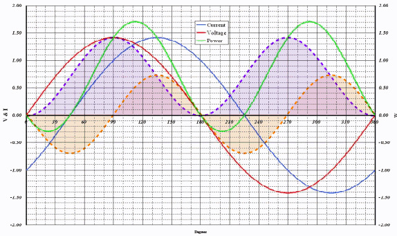
The waveforms you posted show voltage, two currents, their sum, the resulting powers. When voltage and current are of the same polarity, power is shown as positive and it is negative when current and voltage are of opposite polarities. And of course zero when either current or voltage is zero.
It concurs with exactly what I have been saying over the past 500 or so posts.
Maybe persistence works.
:grin:
 

rattus

Senior Member
I didn't. It is just a plot of instantaneous power. Instantaneous voltage times instantaneous current. It's a simple as that.

In my book, literally, it is called "instantaneous reactive power, instantaneous quadrature power, instantaneous reactive volt-amperes, etc." But whatever terms you choose, the equation for p(t) clearly separates the real power from the uh-uh power, and both can be plotted as functions of wt. Their sum is the vi product. Can you deny this obvious fact??
 

Smart $

Esteemed Member
Location
Ohio
I don't disagree with any of that.
The waveforms you posted show voltage, two currents, their sum, the resulting powers. When voltage and current are of the same polarity, power is shown as positive and it is negative when current and voltage are of opposite polarities. And of course zero when either current or voltage is zero.
It concurs with exactly what I have been saying over the past 500 or so posts.
Maybe persistence works.
:grin:
Great that you don't disagree. :cool: But is that the same as agreeing? ;)

Nevertheless, I'm not done... so you (we?) may not be on cloud nine just yet :roll:

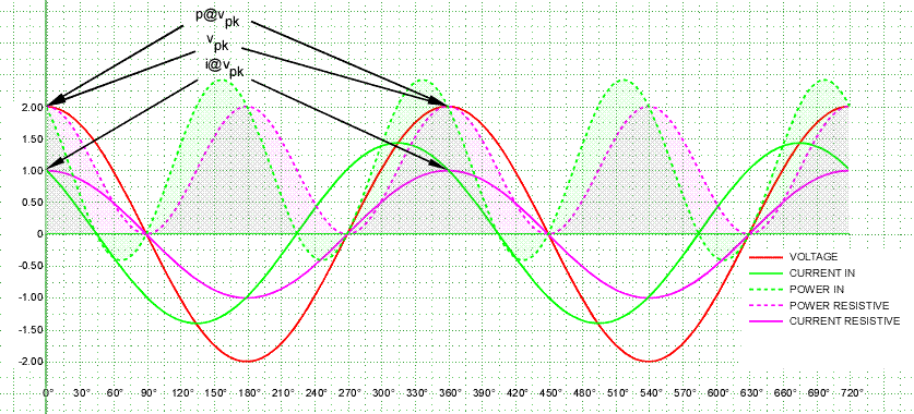
What I have been saying for the past 500 or so posts is that information on the resistive and reactive portions of the input power can be gleaned solely from the input power without the knowledge of what comprises the circuit. First we look at the input power's value at v_pk. Why? Because at v_pk the current is all resistive, for there is no reactive current at v_pk. Since we are evaluating sinusoidal waveforms, we can determine the resistive portion waveform for we need only one point referenced to time to establish the rest of the curve. We can also establish the resistive portion's current, as once we have the power waveform, we just divide by v (note where it intersects with input current). Are you with me so far?

PFVAW8.gif
 

Besoeker

Senior Member
Location
UK
In my book, literally, it is called "instantaneous reactive power, instantaneous quadrature power, instantaneous reactive volt-amperes, etc." But whatever terms you choose, the equation for p(t) clearly separates the real power from the uh-uh power, and both can be plotted as functions of wt. Their sum is the vi product. Can you deny this obvious fact??
P(t) is a continuous function. It describes power as a function of time at every instant in time.
That's obvious I suppose.
It is just the instantaneous product of current and voltage.
It has only one value at each instant. It is the power at that point in time.
It is that power regardless of anything that happens before or after.

Look again at this.

PFC01.jpg


At 45deg in you have 1V, 1A, and 1W.
It is 1W. Just 1W. You can't resolve into real and reactive components. It is just 1W at that instant in time.
 

Smart $

Esteemed Member
Location
Ohio
...

At 45deg in you have 1V, 1A, and 1W.
It is 1W. Just 1W. You can't resolve into real and reactive components. It is just 1W at that instant in time.
...and at 90? you have what appears to be 1.414V, 0A, and 0W. This indicates that the circuit involved is purely reactive, and because the current's waveform leads the voltage's it is more capacitive than inductive.

The topic of this discussion is: Power factor and VA vs Watts. Your graph depicts 0pf, 0VA, and 0W. Regarding the topic, what do you see that can be learned from your graph?

It just amazes me that you can go from...
I don't disagree with any of that.
...to this...
It is just the instantaneous product of current and voltage.
It has only one value at each instant. It is the power at that point in time.
It is that power regardless of anything that happens before or after.

Look again at this.
 

rattus

Senior Member
P(t) is a continuous function. It describes power as a function of time at every instant in time.
That's obvious I suppose.
It is just the instantaneous product of current and voltage.
It has only one value at each instant. It is the power at that point in time.
It is that power regardless of anything that happens before or after.

Look again at this.

PFC01.jpg


At 45deg in you have 1V, 1A, and 1W.
It is 1W. Just 1W. You can't resolve into real and reactive components. It is just 1W at that instant in time.

Bes, your plot is incomplete. See the attached plot which breaks the vi product into its real and reactive portions. The reactive wave averages out to zero while the real wave never dips below zero. Clearly vi is the sum of these two waves. Can you deny this?
 

Smart $

Esteemed Member
Location
Ohio
P(t) is a continuous function. It describes power as a function of time at every instant in time.
That's obvious I suppose.
It is just the instantaneous product of current and voltage.
It has only one value at each instant. It is the power at that point in time.
It is that power regardless of anything that happens before or after.

Look again at this.

...

At 45deg in you have 1V, 1A, and 1W.
It is 1W. Just 1W. You can't resolve into real and reactive components. It is just 1W at that instant in time.
Let us look at your other graph again, instead...

PF07.jpg


First, we know this is overall an inductive load because the current waveform lags the voltage's. At v_pk, voltage appears to be 1.414V and current appears to be 1.000A, thus input power at that instant is 1.414Watts. Since only resistive impedance of the load contributes to current and power at v_pk, we also know this is i_pk of all resistive components of the load. Hence...
p(t)_real = (1.414V*sin(wt)) * (1.000A*sin(wt))​
We also deduce from the v and i data the equation for...
p(t) = (1.414*sin(wt)) * (1.414A*sin(wt–45?))​
From there we just subtract...
p(t)_reactive = p(t) – p(t)_real = (1.414*sin(wt)) * (1.414A*sin(wt–45?)) – (1.414V*sin(wt)) * (1.000A*sin(wt))​
The rest is just a math exercise...

PFVAW9.gif
 
Last edited:

rattus

Senior Member
Now, if all Bes is saying is that you can't tell anything about the circuit from a single measurement, that is a no-brainer, although it is only partially true.

If vi is positive, we can't tell the nature of the circuit.

If vi is negative, we know there is a reactance in the circuit.

But, so what? What does this tidbit have to do with the original question?
 

K2500

Senior Member
Location
Texas
I'm uncertain what you mean by...
... especially the overlap part. Perhaps where the areas under the voltage and current waveforms are concurrent? If so, no. The only readily discernible sign of real power (in the conventional, power-engineering sense ;)) is current other than zero when voltage is at its peak (in sinusoidal waveform analysis).

... and thus power is negative. This can be likened to lifting a block in the air. Work was performed and the power of this occurrence is the rate at which the work happened. If you then drop the block, this can be considered negative power because it is work undone, and the power would be the rate at which the work was undone.


Correct interpretation.
Using that definition I understand the power depicted in -graph post 544- is VAR, and the power at 45 degrees to be one VA.
I say VA because, if the only information I acquire is from that point, I do not have enough information to define the product of volts and amps as anything other than Volt-Amperes.
I hope this is correct, I will return to lurking while I research the nature of energy storage in capacitors and inductors.
 

Smart $

Esteemed Member
Location
Ohio
Correct interpretation.
Using that definition I understand the power depicted in -graph post 544- is VAR, and the power at 45 degrees to be one VA.
I say VA because, if the only information I acquire is from that point, I do not have enough information to define the product of volts and amps as anything other than Volt-Amperes.
I hope this is correct, I will return to lurking while I research the nature of energy storage in capacitors and inductors.
From my perspective, correct... though as the graph depicts a net-capacitive-only load, all values of the vi product would be "VAR", not just at 45?. If information were limited to the vi product at 45?, there would be no way to determine real and/or reactive portions (with respect to the load)... so the VA unit is appropriate in a real power vs. apparent power load analysis.
 

Besoeker

Senior Member
Location
UK
Bes, your plot is incomplete. See the attached plot which breaks the vi product into its real and reactive portions. The reactive wave averages out to zero while the real wave never dips below zero. Clearly vi is the sum of these two waves. Can you deny this?
If it is a parallel RC circuit, the average value of the reactive component wouldn't be zero.
 

Smart $

Esteemed Member
Location
Ohio
Suppose you have 50kVA capacitor on a three phase 480V system, how much current would it take?
I'm guessing about 60A line current, assuming that is the total kvar rating (i.e. not a 3x_ rating) of a 3? delta-connected unit.

Why?
 

rattus

Senior Member
Must be the language barrier:

Must be the language barrier:

If it is a parallel RC circuit, the average value of the reactive component wouldn't be zero.

Bes, you didn't answer the question. Is the plot right or wrong? And, if it is wrong, tell me the reason.

And, did I hear right? The net power to a cap is greater than zero?? Are you saying that the one period average value of a sine wave is not zero? Are you saying this equation is wrong???

p(t) = v(t)*i(t) = [VmIm/2]*[cos(phi) -cos(2wt)cos(phi) + sin(2wt)sin(phi)]
 
Last edited:
Status
Not open for further replies.
Top