You are using an out of date browser. It may not display this or other websites correctly.
You should upgrade or use an alternative browser.
You should upgrade or use an alternative browser.
Energy conservation
- Thread starter gar
- Start date
- Status
- Not open for further replies.
weressl
Esteemed Member
Using these devices for superior energy management is like detective work. When the readout spikes up, just go around and pull the plug on whatever is running to see how much energy is reduced from the readout. It will get the TV watcher off the couch to seek and unplug. I can see where it would be a healthy form of exercise and mental challenge for the individual who is on medication. I myself use an Amprobe.
Again, if it is a kWH indicator, you will not see a 'spike'.
You would need an Amprobe to decide if a device is on or not? Hmmmm.........
kWH
kWH
Bad choice of words on my part. Higher reading would have been more appropriate. Using an Amprobe was a gaufaw. Sorry about that. rbj
kWH
Again, if it is a kWH indicator, you will not see a 'spike'.
You would need an Amprobe to decide if a device is on or not? Hmmmm.........
Bad choice of words on my part. Higher reading would have been more appropriate. Using an Amprobe was a gaufaw. Sorry about that. rbj
weressl
Esteemed Member
Bad choice of words on my part. Higher reading would have been more appropriate. Using an Amprobe was a gaufaw. Sorry about that. rbj
Not really if you are trying to identify a malfunctioning or overloaded machine and that is one part of the energy conservation measure. My issue was mainly with the other statement that reading the consumed kWHr's does not not accomplish much. Looking at kW readings of machines can give you an idea if they perform as 'advertised' or if they use more electricity than you think they do. Two major culprits are refrigerators and AC units, but since they have variable loads it is really difficult to determine their efficiency, especially since their consumption is dependent on the ambient temperature OVER time. The integer of those three values would give you how efficiently those machines perform.
Raising the temperature settings or fridge dials and adding insulation over your water heater and pipes are some things you can control and have greater efect than any measurements you may perform. I just don't believe that tabletop devices would be much help even for instantaneous kW readout. I was waiting for somebody to convince me otherwise with some facts.
Last edited:
My issue was mainly with the other statement that reading the consumed kWHr's does not not accomplish much. Looking at kW readings of machines can give you an idea if they perform as 'advertised' or if they use more electricity than you think they do. Two major culprits are refrigerators and AC units, but since they have variable loads it is really difficult to determine their efficiency, especially since their consumption is dependent on the ambient temperature OVER time. I just don't believe that tabletop devices would be much help even for instantaneous kW readout. I was waiting for somebody to convince me otherwise with some facts.
I certainly agree with your reasoning. Maybe if manufacturer's would put digital readouts to show the current being used would be more conducive to self-monitoring wasteful units. A good example of that would be heat pumps and the resistive heater load override stat controls that are sometimes included with their system.
ohmhead
Senior Member
- Location
- ORLANDO FLA
Well ive got a few questions please were just a simple field electrician here so dont get to technical , when we correct PF we now have more current flow in circuit voltage is raised to near normal applied voltage ? does this not use more power meaning watts ? voltage and current are now closer to each other in phase some what so only a little ac resistance is now limiting and mostly dc resistance of circuit wiring ? so if one corrects PF we really use more power wright or wrong ? so now true power is what is measured by wattmeter of load ? and apparent is nameplate kva of load ? PF is the percent displaced current to voltage of watts used to given watts? If PF is bad your not at normal voltage and so current is lower less wattage used ? These power factor correct energy savor boxes inside is what a capacitor and maybe a choke filter inductor and if its not adjusted to each load its not good in my way of thinking so how can you sell a energy savor box generally on the market to everyone ? It may save pennys or a few dollars but i think it must be tuned to you load you motor load or inductive loads on each circuit ? comments take care
gar
Senior Member
- Location
- Ann Arbor, Michigan
- Occupation
- EE
090312-1857 EST
ohmhead:
Consider a resisitive load of 1 KW with an AC supply voltage of 100 V. These values are just to have convenient numbers. The resistance is 10 ohms. V^2/1000.
The current is 10 A, V/R. The resistor is producing heat from the current thru the resistor.
Now I will put a pure inductance of 10 ohms reactance in parallel with the resistor. This has 10 A flowing thru the inductor independent of the resistive, and this current lags the resistive current by 90 deg. The supply current is the vector sum of these two load currents and has the magnitude of 14.14 A. A pure inductance means it has no losses and therefore no resistive component. Disregarding super conductivity there is no real world pure inductor, but we can can still analyze circuits with the assumption that a pure inductance exists theoretically.
Next remove the inductor and put a pure capacitor with a capacitive reactance of 10 ohms in parallel with the 10 ohm resistor. This capacitive current leads the resistive current by 90 deg. The magnitude of the resulting supply current is 14.14 A. Still only 1 KW of power is dissipated, but the input volt-amperes are 1414. The power factor is 1000/1414 = 0.707, and the arc cosine of 0.707 is 45 deg.
Now put both the inductor and capacitor in parallel with the resistor and the two reactive current vectors cancel one another and the supply current is 10 A. For this particular combination this is called a parallel resonant circuit.
The amount of power dissipated (work done) never changed, but the magnitude of the line current varied from a minimum of 10 A to 14.14 A. During all these experiments the wattmeter reading never changed because it only measures the real power from the supply.
.
ohmhead
Senior Member
- Location
- ORLANDO FLA
Well Gar , we see and understand resistance i know a inductor or a capacitor can cancel there ac resistance or reactance at a tuned frequency not just any frequency . I also understand that the effective value of a ac wave is calculated from the peak value by EFF=0.707 x PEAK V ,or PEAK V =1.41 x EFF V if one is not at resonance frequency then power factor correction is not achieved in my book ? A watt meter measures true power in watts meaning current and voltage in circuit to me if a inductance is in circuit we know its not a pure inductance it does use power in real life this is current flow and watts used along with the resistance of wire in coil of inductance so the wattage is or has to be measured ? we add capacitance to cancel the ac resistance or reactance but if your not at resonance or at a TUNED FREQUENCY of both coil or capacitor you are not correcting PF what iam asking is how can a person sell a energy saving device over the counter and say it saves money on your bill ? It doesnt and in real life i do think pf is a waste of time i think even with a bad pf you just might save a little bit more on your power bill i also think harmonics are bad but you can actually save money with lots of harmonics it chops up the wave watts used are not actual watts seen by meter ? comments Gar best to ya see ya after work today
gar
Senior Member
- Location
- Ann Arbor, Michigan
- Occupation
- EE
090313-0736 EST
ohmhead:
When one does circuit analysis basic ideal elements are used. This means if I have a real world inductor it will be separated into its equivalent components for analysis. This separation can be simple or very complex. At low frequencies a real world inductor typically would be separated into pure inductive and resistive components, and capacitance might be neglected. The equivalent circuit can be series or parallel.
You missed the point of my comments in my post #27. What I was trying to do in this post was to was show that a load with a fixed power output, the resistor that did not change, had the same power input as the output whether the inductive component was existent or not, and compensated or not. Note: ideal inductors or capacitors do not dissipate any energy. They simply store energy or send it somewhere else.
You need to find some good books on circuit analysis, and study these. One such book is "Analysis of A-C Circuits", by Melville B. Stout, 1952. This book in parts requires a knowledge of differential and integral calculus, and differential equations. It is also probably virtually impossible to find a copy. Not yet scanned by Google. The only library listed by Google where a copy exists is the University of Michigan. You need to look in your local libraries for similar books. Try to find something that provides an intuitive approach.
When you do not have equal inductive and capacitive reactances at a particular frequency then you are somewhere on the side of the resonance curve. In general when correcting power factor you do not want to exactly balance out the reactive components at line frequency because this puts you at the peak of the resonance curve and under transient conditions, these always exist, ringing at line frequency will be a maximum. As power factor gets closer to 1.0 the inductive and capacitive components are more nearly balanced.
A note on your posts. It would help readability if your were to break your thoughts into paragraphs. This might mean you need a double carriage return. You can experiment with what is needed by doing a preview of your post.
.
ohmhead
Senior Member
- Location
- ORLANDO FLA
Well Gar thanks for the input .
I have lots of books on ac dc basics just like to hear what others think about on different subjects.
power savors energy devices these are old age electrical but new age products .
thanks for the time explaining Gar i will ask questions
we like you opinions on these and the helpful details of your post .
Take care best to ya
- Location
- San Francisco Bay Area, CA, USA
- Occupation
- Electrical Engineer
090309-2146 EST
There have been many threads started about energy reduction devices and the vast majority of these devices are frauds. Namely PF correction where it will have no effect on the customer's bill.
A real and simple way to reduce energy consumption and save money is to reduce any unnecessary loads. Turn lights and other moderate power consuming devices off when not needed.
Obviously a measuring tool can be of assistance to achieve this goal...
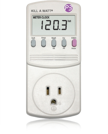
Back to the original topic of this thread, I recently used a few of these in an industrial setting to look at power consumption of some 120V test fixtures. Great little devices, relatively cheap too. This isn't a specific endorsement, just a testimonial.
http://www.p3international.com/products/special/P4400/P4400-CE.html
SAC
Senior Member
- Location
- Massachusetts
090312-1857 EST
The amount of power dissipated (work done) never changed, but the magnitude of the line current varied from a minimum of 10 A to 14.14 A. During all these experiments the wattmeter reading never changed because it only measures the real power from the supply.
.
And the reason anyone (i.e., the POCO) cares - a resistor in series (their transmission and distribution network) with such an inductive network experiences the larger current, and does dissipate more "real" power due to the larger current. Even though you aren't "using" more power, you are causing them to need to generate, transmit, and distribute more power in order to deal with your poor power factor.
gar
Senior Member
- Location
- Ann Arbor, Michigan
- Occupation
- EE
090313-1832 EST
SAC:
My analysis was not intended to describe the distribution system, but rather to show how to look at the fundamental components at the load.
Sure, if output load power remains constant and you look at the effect of the power factor of that load on the distribution system, then from a power loss in the supply and distribution system you want minimize the reactive current component.
.
SAC
Senior Member
- Location
- Massachusetts
090313-1832 EST
SAC:
My analysis was not intended to describe the distribution system, but rather to show how to look at the fundamental components at the load.
Sure, if output load power remains constant and you look at the effect of the power factor of that load on the distribution system, then from a power loss in the supply and distribution system you want minimize the reactive current component.
.
Sorry - your description was great. I just thought I'd comment on the major reason people care about a poor power factor - the POCO loses money.
gar
Senior Member
- Location
- Ann Arbor, Michigan
- Occupation
- EE
090319-1306 EST
Last week I order one of the "TED" units, and it arrived today.
The results of some quick tests:
The unit is for a 120-0-120 supply up to 200 A, and only measures voltage from neutral to one hot line. Therefore, that voltage is used to calculate power on both sides of neutral.
Data is quantized to 1 second increments, but appears to be averaged within the 1 second period.
With a 75 W bulb that I have perviously measued at 75 W at 120 V the TED reading was 0.080 or 0.070 KW depending upon a slight voltage adjustment.
Adding a 25 mfd capacitor in parallel with the lamp produced no change in the power reading.
Using their software to plot voltage and power quantized to 1 second worked well.
.
SAC
Senior Member
- Location
- Massachusetts
I've been considering buying such a product, or building my own. Unfortunately, building my own seems to be more expensive (and time consuming) than buying what is available - though I could then have complete control over the feature set. For instance, I'd like to be able to graph over days, weeks, or years (like I currently do with my indoor and outdoor temp) the power consumption at intervals of 5 minutes or so.
In all, how satisfied are you with your TED?
Thanks!
-Shawn
In all, how satisfied are you with your TED?
Thanks!
-Shawn
gar
Senior Member
- Location
- Ann Arbor, Michigan
- Occupation
- EE
090319-2058 EST
Shawn:
So far the "TED" is clearly a useful tool from my quick checks.
Certainly it is probably adequate for the purpose of having some idea of what is the real time load power and voltage.
Since full scale is 200 A they have chosen to quantize at 10 W, or about 0.1 A in 200 A.
The transmitter in the main panel outputs voltage, derived from only one side of the neutral, and probably power, I doubt that it is current at this point because phase information would also have to be sent. The power is from both phases. No wires are required because carrier current transmission on one phase is used. They seem to be doing a good job of measuring power based on my experiment of adding the capacitor in parallel with a lamp.
The transmitted data goes to the display unit where there is processing and some memory storage. One second sample data is not stored here, but rather some accumulation is. For an instantaneous display of power this is OK. This data is updated once each second.
There is a USB output on the display box for connection to a computer where their optional software resides. This software provides memory and processing of data. This is the least satisfactory part of the system. If you figure out the communication protocol, then you can write your own software. Later I may comment more on this.
They have a real time plot quantized to 1 second that is limitedly useful. The voltage scale is fine, but the power scale does not seem to be adjustable. Thus, 75 W is hardly noticeable, and 250 W is is a small blip.
Getting two channels of current converted to real power and summed, and one channel of voltage is worth the price.
A lot of the functions provided are sort of useless garbage. I do not need KWH converted to $, or to CO2.
.
gar
Senior Member
- Location
- Ann Arbor, Michigan
- Occupation
- EE
090320-1158 EST
Shawn:
A correction. I can change the power scaling on the graphing display. It seems the software does not always respond to a change in the SETTINGS page. I think they have some minor software bugs. However, it is looking like a useful tool. It is interesting to watch the voltage changes with no load changes, and then the effects with load change.
Currently my tests are on the bench. With outlet strips and plugs in series I had about a 4 V drop at the bench with a 1500 W heater load.
Our main panel is 200 A 240 V three phase open delta. The air compressor and a large belt sander are connected close to the main panel. When the sander turned on the inrush current produced about a 2 V momentary drop, and the 5 HP positive displacement air compressor produced about 4 V drop. Then we tried the 10 HP screw compressor which has no initial load except inertia and some friction and that drop was about 1 V.
.
Mr.Sparkle
Senior Member
- Location
- Jersey Shore
I was looking at the TED 1001 just this week from a link posted in another thread. I think I might pick one up due to the relatively low cost of the unit.
gar
Senior Member
- Location
- Ann Arbor, Michigan
- Occupation
- EE
090331-2050 EST
Measurement of difference between the two current transducers supplied with the TED 1001 I ordered.
Energy, Inc. claims a +/-2% of reading accuracy. I do not have a means to do high accuracy power measurement at high current so I can not do a test on their absolute accuracy claim. The above difference accuracy can be consistent with their claim.
The TED only measures the voltage on one side of neutral. This would also be part of the real accuracy.
In general the device looks quite good.
.
Measurement of difference between the two current transducers supplied with the TED 1001 I ordered.
Code:
[FONT="Courier New"]Current  Power   Diff Power    % Diff
   A       W         W

  208     25k       310          1.2
  125     15k       210          1.4
   83     10k       110          1.1
   42      5k        50          1.0
   12      1.5k      20          1.3[/FONT]
Energy, Inc. claims a +/-2% of reading accuracy. I do not have a means to do high accuracy power measurement at high current so I can not do a test on their absolute accuracy claim. The above difference accuracy can be consistent with their claim.
The TED only measures the voltage on one side of neutral. This would also be part of the real accuracy.
In general the device looks quite good.
.
- Status
- Not open for further replies.