Crossman, don't get hung up on the term "cutting". Just think of an ideal transformer where all the flux lines exist within the core. Now imagine that the total flux, phi, changes in a sinusoidal manner. Then dphi/dt is also a sinusoid. Then the emf induced in any single turn or number of turns is a sinusoid as well.
You are using an out of date browser. It may not display this or other websites correctly.
You should upgrade or use an alternative browser.
You should upgrade or use an alternative browser.
"Mystery Current" burns up cable splitters
- Thread starter crossman
- Start date
- Status
- Not open for further replies.
crossman
Senior Member
- Location
- Southeast Texas
Rattus, I definitely have a hang-up about "flux cutting wire" because that is what I was taught and they way I viewed things for 25+ years now. And, I am definitely the type of person who asks "why does it work like that" versus "what is the mathematics of it?" I think both viewpoints have their place and a person who understands both viewpoints is all the wiser.
Because of you and others, I am definitely getting to glimpse both sides of the fence, and am happy as can be right now.
I know there are subjects in physics which simply can't be visualized, such as the proposed ten dimensions which may unify the 4 fundamental forces in physics. A rough quote from a book I read "it is impossible to visualize ten dimensions so don't try. The math provides the proper framework" I admit I have a distaste for statements like that, because, by god, I want to understand HOW it works!
I think my post #79 is a good summation of cutting flux versus changing flux density. I think they are equivalent, and I am thinking it can be shown mathematically based on 100,000,000 flux lines cutting a conductor in ones second produces 1 volt. What it boils down to is that the change in flux density is exactly equal to the number of net flux lines cutting the loop.
Of course, I realize that the "flux lines" are not real, they are just a representation of the magnetic field.
winnie
Senior Member
- Location
- Springfield, MA, USA
- Occupation
- Electric motor research
The concept of flux cutting conductors is quite useful, and IMHO is 'more fundamental' in the sense that there are problems which can be solved using flux cutting which cannot be solved using 'flux contained by a loop' without funky machinations. See, for example, the homopolar generator, where there are no loops in which the flux changes.
That said, for many applications, it is easier to solve the problem from the point of view of the changing flux enclosed by the loop, and for most situations the two approaches are equivalent.
-Jon
That said, for many applications, it is easier to solve the problem from the point of view of the changing flux enclosed by the loop, and for most situations the two approaches are equivalent.
-Jon
ghostbuster
Senior Member
- Location
- Great White North
More newsletter comments(final?) added-
http://mikeholt.com/newsletters.php?action=display&letterID=507
http://mikeholt.com/newsletters.php?action=display&letterID=507
crossman
Senior Member
- Location
- Southeast Texas
Ghostbuster, you mentioned that the flux densities around the houses were between 100 to 200 milligauss.
I found some formulas for calculating the magnetic fields around 60 Hz power lines. There is a formula for balanced 3-phase situations, and unbalanced situations. These were found at http://www.euro-emc.co.uk/datasheets/Magnetic/EMF%20Fundamentals.pdf.
Balanced Phase Equation: B = (3.46 x I x d) / r^2
where
B = flux density in milligauss
I = Amps in each phase
d = distance between phase conductors on towers in meters
r = distance from nearest phase conductor in meters
Unbalanced Current Equation: B = (2 x I) / r
where
B = flux density in milligauss
I = unbalanced amps
r = distance from nearest phase conductor in meters
We know that the transmission line in question had to either be balanced or unbalanced, so let's do some calculations assuming balanced, then unbalanced. Assume RMS values.
If we had balanced phases: We can calculate the current in each phase of the transmission line.
B = (3.46 x I x d) / r^2
Given:
B = 150 = flux density in milligauss (splitting the difference of 100-200)
I = Amps in each phase = unknown, we will solve for this
d = 20 feet = 6 meters = distance between phase conductors on towers in meters (The 6m is an assumption based on visual inspection of typical high tension lines. If you have better data, let me know. How far apart where the phases?)
r = 70 feet = 21.2 meters = distance from nearest phase conductor in meters (again, this is an asumption, assuming the nearest conductor was 60 feet in the air vertically and 40 feet horizontally from the backyard. If you have better data, let me know. I would think the distance was actually further than this.)
150 = (3.46 x I x 6) / 449.4
use basic algebra
I = 3247 amps in each phase at 230 kV 60hz required to produce 150 milligauss at 70 feet
This seems like an awful lot of current on the transmission line. Of course, this is based on my ignorance - I just wouldn't expect it to be that high. So, I researched on the net, and typical current values of 230 kV lines were 200 to 900 amps. I did find one that had an emergency rating of 1600 amps. Do you have data on how much current the 230 kV lines were actually carrying?
Now let's assume there was a current inbalance that was the major contributing factor:
B = (2 x I) / r
Given:
B = 150 = flux density in milligauss (splitting the difference of 100-200)
I = Amps in each phase = unknown, we will solve for this
r = 70 feet = 21.2 meters (same as in previous formula)
150 = (2 x I) / 21.2
basic algebra
I = 1590 amps unbalanced current at 230 kV 60 hz required to produce 150 milligauss at 70 feet.
Again, this seems like an extremely large imbalance to have between phases. I would think the POCO would have noticed this and would have corrected it long ago.
Anyone see any issues above? Ghostbuster? Yes, some of the data is estimated, but surely it is in the ballpark. Of course I have follow-up coming, but I'll wait to see if anyone is still interested in this. The question at the moment is "Could the transmission line currents be THAT high?"
ghostbuster
Senior Member
- Location
- Great White North
crossman said:Ghostbuster, you mentioned that the flux densities around the houses were between 100 to 200 milligauss.
This seems like an awful lot of current on the transmission line. Of course, this is based on my ignorance - I just wouldn't expect it to be that high. So, I researched on the net, and typical current values of 230 kV lines were 200 to 900 amps. I did find one that had an emergency rating of 1600 amps. Do you have data on how much current the 230 kV lines were actually carrying?
The question at the moment is "Could the transmission line currents be THAT high?"
Crossman:
You made 1 fatal assumption.
In all your calculations:
You are assuming 1 3phase 230 kv.circuit was present.
How many 3 phase circuits actually existed at this site??
Aside: that is an excellent Primer link on understanding magnetic fields.
I would highly recommend it for anyone that is interested in magnetic and electric fields.
crossman
Senior Member
- Location
- Southeast Texas
First, please let me express one thought: I simply am trying to increase my knowledge of the situation. My admitted unlearned instinct is that the situation seems extraordinary. I am trying to understand how the situation can happen in reality. I am desiring to increase my knowledge for the sake of knowledge. To do this often requires us to ask questions of other more knowledgable people and to hopefully get answers. It may require us to make hypotheses that can be debated upon the merits of the evidence. I am not attempting to prove anyone wrong. This is not an antagonistic battle.
I asked the question: "Could the transmission line currents be THAT high?
I admitted that my "instinct" told me that 3247 amps seemed very high, and I admitted I had no sound basis in rejecting the number. There is no "fatal flaw" to be considered. Before I can continue my thoughts, I need an approximation of the current in the transmission lines. If it is 3247 amps in multiple circuits, that is acceptable and I will continue from there.
Since you seem to be involved in the study, can you provide any more data such as the the configuration of the transmission lines and distances between conductors? Can you further define any of the data above which I speculated on? Can you give any other data?
As always, in scientific endeavors as in any other field, extraordinary claims require extraordinary evidence. If anyone is interested , I will be grateful.:smile:
Thanks for any further help you can give.
Crossman:
I'm looking at the diagram your post #80. Assume the B field is uniform, and assume the entire coil is inside the B field. Then moving the coil through the field wouldn't produce any voltage or current. That's basically what you have been saying all along. On both sides of the coil, the current would tend flow in the upward direction. So they would cancel each other. And the amount of flux crossing the area of the coil wouldn't change either since the field is uniform.
The more I think about it, we are visuallizing this in different ways, but they are equivalent. You prefer to think about the flux cutting the wire. I prefer to think about the change in flux through the area of the coil.
I think it might be pretty easy to prove they are the same thing. You are visuallizing a strong magnetic field at the source, and then thinking about the difference in strength as it cuts through one wire, and another wire farther away.
I am visualizing a weaker magnetic field to start with. One that starts inside the coil of wire and moves outward, cutting the coil of wire all in the same direction. I don't have time to prove (or disprove) that the two are equal. But it would make sense if that were the case.
Steve
crossman
Senior Member
- Location
- Southeast Texas
Hey Steve!
As you say, I believe the two ways of looking at it are exactly the same. Actually, I am 100 percent convinced of it. I also agree with you about me looking at a stronger overall field and its effect on the wires, whereas you are looking at a weaker field affecting the loop as a whole. Both are equivalent, and to me, was very instructive.
Also, please take a second to go through post #79. That is what convinced me that the methods are equivalent.
But then that got me to thinking. See the new thread "Hey Mr. Farady! Explain this" concerning something I thought of about the flux density viewpoint.
crossman
Senior Member
- Location
- Southeast Texas
Bump for Ghostbuster:
crossman said:Since you seem to be involved in the study, can you provide any more data such as the the configuration of the transmission lines and distances between conductors? Can you further define any of the data above which I speculated on? Can you give any other data?
As always, in scientific endeavors as in any other field, extraordinary claims require extraordinary evidence.
Thanks for any further help you can give.
iaov
Senior Member
- Location
- Rhinelander WI
The universe is not only wierder than we had imagined,it is wierder than we can imagine. Stephen Hawkings:smile:crossman said:Rattus, I definitely have a hang-up about "flux cutting wire" because that is what I was taught and they way I viewed things for 25+ years now. And, I am definitely the type of person who asks "why does it work like that" versus "what is the mathematics of it?" I think both viewpoints have their place and a person who understands both viewpoints is all the wiser.
Because of you and others, I am definitely getting to glimpse both sides of the fence, and am happy as can be right now.
I know there are subjects in physics which simply can't be visualized, such as the proposed ten dimensions which may unify the 4 fundamental forces in physics. A rough quote from a book I read "it is impossible to visualize ten dimensions so don't try. The math provides the proper framework" I admit I have a distaste for statements like that, because, by god, I want to understand HOW it works!
I think my post #79 is a good summation of cutting flux versus changing flux density. I think they are equivalent, and I am thinking it can be shown mathematically based on 100,000,000 flux lines cutting a conductor in ones second produces 1 volt. What it boils down to is that the change in flux density is exactly equal to the number of net flux lines cutting the loop.
Of course, I realize that the "flux lines" are not real, they are just a representation of the magnetic field.
I just have a problem visualizing the lines moving in the case of a transformer. I've always considered the lines to be an aid in visualizing the flux density - more lines, higher density. Sort of like lines on a topographic map being closer together meaning a steep hill.crossman said:I think my post #79 is a good summation of cutting flux versus changing flux density. I think they are equivalent, and I am thinking it can be shown mathematically based on 100,000,000 flux lines cutting a conductor in ones second produces 1 volt. What it boils down to is that the change in flux density is exactly equal to the number of net flux lines cutting the loop.
I visualize the changing flux as the flux represented by a single line changing flux value. So, in my visualization, the flux represented by a single line inside the transformer coil would be something like 20?sin(2?pi?f?t) that varies sinusoidally with time. I can't get my mind around all of these lines moving in and out sinusoidally.
I think the lines cutting imagery is best when thinking about motors and generators where something is actually moving. The flux changing within an area imagery is best when thinking about transformers and coils next to transmission lines.
ELA
Senior Member
- Occupation
- Electrical Test Engineer
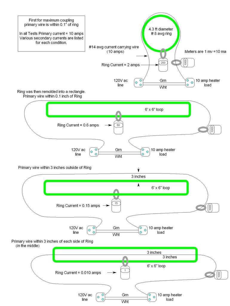
Here is a follow up from the test I mentioned way back in post #18. This was around the discussion about canceling fields in opposite sides of the ring.
I refashioned the same test circular ring into a rectange.
While the first test demonstarted good coupling by having all of the field encompasing the ring in the same direction the last shows the field cancelations when the field intercepts the opposite sides of the ring equally but in opposite directions.
crossman
Senior Member
- Location
- Southeast Texas
ELA, thank you for continuing the experiments and your diagrams are beautiful. And, they validate what we have been saying earlier.
I am considering doing similar experiments but with about 100 amps in the primary wire to see how far away the loop can be to still induce significant current.
The way I can easily get 100 amps is: I have a variable 120 volt, 20 amp supply. I also have a fairly large 120 to 12 xfmr which provides a substantial current out of the secondary. Adjusting the primary voltage will control the amount of current through the primary loop.
We use the above set-up to demonstrate what happens to various types of insulated conductors when the conductors are overloaded. We've gotten up to 180 amps out of it. (At 180 amps, the insulation melts off of a #12 wire, the wire glows red but it doesn't burn in half!)
ELA
Senior Member
- Occupation
- Electrical Test Engineer
Crossman,
I would have thought that you would have been ready to call this one - "busted"? At least the 2 amps induction into the test ring part of it?
100 amps in a single conductor will be a vary large field close-in.
Make sure there are not any flies near you just in case!")
I would have thought that you would have been ready to call this one - "busted"? At least the 2 amps induction into the test ring part of it?
100 amps in a single conductor will be a vary large field close-in.
Make sure there are not any flies near you just in case!
crossman
Senior Member
- Location
- Southeast Texas
ELA, I an tending toward the "busted" side of the issue. However, I am still keeping an open mind and hoping for some more data from the interested parties.
Since we haven't gotten further data, I will continue my train of thought with calculations based on the amperages given in a previous post. I was going to wait for ghostbuster to give some more data so we could be more accurate, but so far the data has been extremely vague.
If the transmimssion lines were carrying balanced 3240 amps then the flux density at 70 feet very well could have been at 150 milligauss.
Alternatively, assuming an unbalanced current in the t-lines was the culprit, the unbalance would be approx 1590 amps.
Both of the above figures are based on my speculation of the unknown data. I am still hoping for further refinements.
Now consider the five foot loop optimally oriented to the power lines with one side of the loop at 70 feet and the other at 75 feet.
The loop at 70 feet is experiencing 150 milligauss. But what about the loop at 75 feet? The net flux to cause current flow is going to be the milligauss at 70 feet minus the milligauss at 75 feet.
Doing the math, I get:
balanced 3247 amps causes 131 milligauss at 75 feet
unbalanced 1590 amps causes 140 milligauss at 75 feet
So, assuming balanced current of 3247 amps, we have 19 milligauss on the loop.
Assuming unbalanced 1590 amps, we have a net flux of 10 milligauss on the loop.
Can this small amount of flux cause the 2 amps? Somebody give me a hand with the formula for this.
If 19 milligauss can cause 2 amps in the loop, then I will be satisfied that the situation happened as written.
crossman
Senior Member
- Location
- Southeast Texas
Oh...
Yeah, I hope I don't get cancer or something.
I need to go back to that link that gives flux based on amps in the wire to see what 100 amps can do.
ELA said:100 amps in a single conductor will be a vary large field close-in. Make sure there are not any flies near you just in case!
Yeah, I hope I don't get cancer or something.
I need to go back to that link that gives flux based on amps in the wire to see what 100 amps can do.
winnie
Senior Member
- Location
- Springfield, MA, USA
- Occupation
- Electric motor research
crossman said:The loop at 70 feet is experiencing 150 milligauss. But what about the loop at 75 feet? The net flux to cause current flow is going to be the milligauss at 70 feet minus the milligauss at 75 feet.
You are misusing your units here.
Gauss is a unit of flux density http://www.unc.edu/~rowlett/units/dictG.html#gauss representing one Maxwell per square centimeter http://www.unc.edu/~rowlett/units/dictM.html#maxwell and just to tie things back to 'lines', a Maxwell is just another name for a Line
http://www.unc.edu/~rowlett/units/dictL.html#line
The integral of flux density over area give you a number of lines.
The flux density times the loop area will tell us the number of lines that managed to 'cut' one side of the loop, but which didn't manage to also 'cut' the other side. In other words, the difference that you are trying to take must be done with the total magnetic flux that makes it past a point, not the flux density. But the flux density integrated over the loop area will give you the difference that you are trying to calculate; if you assume constant flux density, then the flux density times the loop area is the difference that you want.
-Jon
crossman
Senior Member
- Location
- Southeast Texas
Thank you for pointing out the discrepancies, Jon. I agree that I was mixing and matching terms and units fairly liberally out of my ignorance and lack of rigor.
The formulas I used above give an answer that is Amps/Meters. On the website where I obtained the info, they said that milligauss is measured in Amps per Meter. As you point out, there is a difference between "flux" and "flux density" and other terms I was mixing.
So given that 150 milligauss exists at 70 feet and 131 milligauss exists at 75 feet, what would we have to do to calculate the induced current in a five foot loop of #4 wire where the closest edge is at 70 feet and the farthest edge is at 75 feet?
Could it be 2 amps?
- Status
- Not open for further replies.