If the equation is essentially the definition, how can it not hold for nonlinear loads???... As for your equation for power factor, it holds good for linear loads, but not for non linear loads.
You are using an out of date browser. It may not display this or other websites correctly.
You should upgrade or use an alternative browser.
You should upgrade or use an alternative browser.
Single Phase current draw for a 3 phase output VFD: technical discussion
- Thread starter Jraef
- Start date
- Status
- Not open for further replies.
The definition does not take into account the distortion introduced by non linear loads and so not applicable in case of non linear loads.If the equation is essentially the definition, how can it not hold for nonlinear loads???
As I mentioned earlier. Power factor is just a number to correct VRMS*ARMS to equal P. You only run into a problem when you make the errant assumption that the power triangle applies to all scenarios.The definition does not take into account the distortion introduced by non linear loads and so not applicable in case of non linear loads.
Correct. I was misled by Gar's use of term 'real power' in his equation. If by real power is meant total actual power including that due to distortion loss, then his equation is okay.As I mentioned earlier. Power factor is just a number to correct VRMS*ARMS to equal P. You only run into a problem when you make the errant assumption that the power triangle applies to all scenarios.
gar
Senior Member
- Location
- Ann Arbor, Michigan
- Occupation
- EE
170618-1047 EDT
Smart $:
Knowing that you have a calculus background makes our discussions much easier.
I would like to treat the complete VFD as two black boxes. One is the DC supply, and for simplicity assume it has constant output voltage and zero output impedance, and can absorb energy. A large capacitor with appropriate trickle charge fits this criteria. Any DC source that meets that criteria can be used. The other box is the converter that takes a DC input and provides whatever voltage and current the end load requires.
The said other box (the converter) will always have a constant input voltage, and its input current will be whatever is required. I expect the input current to vary with time. The instantaneous power is V*i. The average power over some time period T is V*Iave over the time period T.
The power factors looking into said other box, or into its load can be whatever is existent. We don't care.
The only requirement on the said first box is that its average input power over T equals its average output power over T, such that excessive output ripple does not occur. The instantaneous input current does not need to track the instantaneous output current. The instantaneous input current will be whatever the said first box circuitry requires. For constant load power on the DC supply (first box output) the said first box will have the same input power factor which is defined by its circuitry independent of any changes in final load power factor.
.
:?170618-1047 EDT
Smart $:
Knowing that you have a calculus background makes our discussions much easier.
I would like to treat the complete VFD as two black boxes. One is the DC supply, and for simplicity assume it has constant output voltage and zero output impedance, and can absorb energy. A large capacitor with appropriate trickle charge fits this criteria. Any DC source that meets that criteria can be used. The other box is the converter that takes a DC input and provides whatever voltage and current the end load requires.
The said other box (the converter) will always have a constant input voltage, and its input current will be whatever is required. I expect the input current to vary with time. The instantaneous power is V*i. The average power over some time period T is V*Iave over the time period T.
The power factors looking into said other box, or into its load can be whatever is existent. We don't care.
The only requirement on the said first box is that its average input power over T equals its average output power over T, such that excessive output ripple does not occur. The instantaneous input current does not need to track the instantaneous output current. The instantaneous input current will be whatever the said first box circuitry requires. For constant load power on the DC supply (first box output) the said first box will have the same input power factor which is defined by its circuitry independent of any changes in final load power factor.
.
Better yet... :slaphead:
gar
Senior Member
- Location
- Ann Arbor, Michigan
- Occupation
- EE
170618-1313 EDT
Sahib:
The equation I provided is a definition. It applies to any two terminal device, linear or nonlinear. And the Vrms and Irms are really RMS values no matter what are the waveforms. Is the equation always useful or meaningful? Most likely not.
The wording "real power" is because some people do not read the word "power" as meaning heat or physical work. And it is the average real power over the same time period as that of the RMS measurements.
This is the power read on a true wattmeter.
.
gar
Senior Member
- Location
- Ann Arbor, Michigan
- Occupation
- EE
170618-2226 EDT
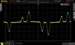
This post is about the line current of one phase of a three phase source to one of our HAAS CNC mills. This is one wire to the input to the HAAS vector spindle drive. There are only three power wires to the drive.
Our power source is two pole mounted transformers wired as a 240 V open delta. There are 300 to 400 feet of lines from the transformers to the machinre. I judge the voltage and phase balance may not be real good based upon th current plot below.
It was most convenient to run the spindle at 3500 RPM and no additional mechanical load. The machine is an advertized 20 HP, and under no machining load the HAAS load meter read 15%
A Fluke Hall device current probe was used to measure current on the 2 V per 20 A range.
The plot is a single shot. Repetitive plotting shows considerable variation in the peaks, but the unbalance was still evident. This is nothing close a sine wave current signal and thus a low power factor.
.
.

.
This post is about the line current of one phase of a three phase source to one of our HAAS CNC mills. This is one wire to the input to the HAAS vector spindle drive. There are only three power wires to the drive.
Our power source is two pole mounted transformers wired as a 240 V open delta. There are 300 to 400 feet of lines from the transformers to the machinre. I judge the voltage and phase balance may not be real good based upon th current plot below.
It was most convenient to run the spindle at 3500 RPM and no additional mechanical load. The machine is an advertized 20 HP, and under no machining load the HAAS load meter read 15%
A Fluke Hall device current probe was used to measure current on the 2 V per 20 A range.
The plot is a single shot. Repetitive plotting shows considerable variation in the peaks, but the unbalance was still evident. This is nothing close a sine wave current signal and thus a low power factor.
.
.
.
Attachments
Last edited:
Interesting....... This is nothing close a sine wave current signal and thus a low power factor.
...
I hear your claim of a low power factor but see no proof. And if you say the proof is in the plot, I'll ask where? I see no rms current determination. You can't determine power factor without it.
Now even if you do manage to show proof, I will note that you took your measurements while the motor is relatively unloaded (15% of 20HP... 3HP to turn a spindle???) when the motor power factor is at its worst. Don't forget the debate is whether or not a VFD improves power factor (at least I think it is... its been kind of hard to keep track of what's actually being debated
") ). To adequately compare, you must determine the power factor of both the input and output for the same period of time... and preferably several examples depicting the same (to demonstrate repeatability) and also at differing amounts of motor loading.
). To adequately compare, you must determine the power factor of both the input and output for the same period of time... and preferably several examples depicting the same (to demonstrate repeatability) and also at differing amounts of motor loading.While you're at it, and for a fair overall comparison, determine the power factor atof the same motor at the same differing amounts of loading when the motor is run across the line, i.e. connected without the VFD.
What it amounts to is, we'd need an electrical testing lab and all the necessary equipment to even come close to settling the debate. :slaphead:
Interesting...
I hear your claim of a low power factor but see no proof. And if you say the proof is in the plot, I'll ask where? I see no rms current determination. You can't determine power factor without it.
Now even if you do manage to show proof, I will note that you took your measurements while the motor is relatively unloaded (15% of 20HP... 3HP to turn a spindle???) when the motor power factor is at its worst. Don't forget the debate is whether or not a VFD improves power factor (at least I think it is... its been kind of hard to keep track of what's actually being debated
While you're at it, and for a fair overall comparison, determine the power factor atof the same motor at the same differing amounts of loading when the motor is run across the line, i.e. connected without the VFD.
What it amounts to is, we'd need an electrical testing lab and all the necessary equipment to even come close to settling the debate. :slaphead:
Here ya go....
GRAPHIC HARMONIC ANALYSIS V(av) 270.1
I(rms) 340 1.220208208
Supply Voltage (V) 267 I(h) 326 367 0.959301243
Delay angle (deg) 42 95.9%
DC Choke (mH) 2
Initial Current (A) 380.0
Choke ripple (A) 326.43 102
Choke ripple (pk-pk) (A) 53.9 13%
Average Current (A) 415.2 338.8
Angle Rect 1 Vmean I inst pk-pk Iac A1 B1 An Bn R.M.S Rads
378 270 380 54 380 1 1
0 369 99 383 0 0 0 0 0 0 -4 0 -8 2460 A/ms
1 368 98 385 0 0 0 0 0 0 -12 0 -1 0.055555556
2 366 96 388 0 0 0 0 0 0 -20 0 -2 0.154471545
3 365 95 391 0 0 0 0 0 0 -28 0 -2 2.780487805
4 363 93 393 0 0 0 0 0 0 -36 0 -2
5 361 91 396 0 0 0 0 0 0 -44 0 -2
6 359 89 398 0 0 0 0 0 0 -52 0 -2
7 357 87 401 0 0 0 0 0 0 -60 0 -2
8 355 85 403 0 0 0 0 0 0 -68 0 -2
9 353 82 405 0 0 0 0 0 0 -76 0 -2
10 350 80 408 0 0 0 0 0 0 -84 0 -2
11 348 78 410 0 0 0 0 0 0 -92 0 -3
12 345 75 412 0 0 0 0 0 0 -99 0 -3
13 342 72 414 0 0 0 0 0 0 -107 0 -3
14 339 69 416 0 0 0 0 0 0 -115 0 -3
On the other hand, you could just take my word for it.
gar
Senior Member
- Location
- Ann Arbor, Michigan
- Occupation
- EE
170619-0807 EDT
Smart $:
From your post #309
Until you can understand that a large enough DC bus filter capacitor is an isolator between the output load power factor of some device hung at the VFD output and the input power factor to the DC supply, then we are at an impasse in communication.
I was willing to define the conditions under which I did the test. I would have to write a special program and waste metal to put a full load on the motor. The only purpose of my test on some arbitrary real production machine (at the time this HAAS machine was built I believe their production was about 10,000 CNCs per year) was to look at the input current under 3 phase operation and see if the current was close to a sine wave. The waveform was nothing close to a sine wave.
I am willing to believe that some VFDs being built today have good (high, near unity) power factors. And we probably should be going in that direction, but show me their waveforms.
.
Smart $:
From your post #309
The low power factor proof is in the waveform shape. You have said you studied calculus. So figure out an estimate of RMS and full wave rectified average current for this waveform, then compare that ratio to the same ratio for a sine wave.I hear your claim of a low power factor but see no proof. And if you say the proof is in the plot, I'll ask where? I see no rms current determination. You can't determine power factor without it.
Until you can understand that a large enough DC bus filter capacitor is an isolator between the output load power factor of some device hung at the VFD output and the input power factor to the DC supply, then we are at an impasse in communication.
I was willing to define the conditions under which I did the test. I would have to write a special program and waste metal to put a full load on the motor. The only purpose of my test on some arbitrary real production machine (at the time this HAAS machine was built I believe their production was about 10,000 CNCs per year) was to look at the input current under 3 phase operation and see if the current was close to a sine wave. The waveform was nothing close to a sine wave.
I am willing to believe that some VFDs being built today have good (high, near unity) power factors. And we probably should be going in that direction, but show me their waveforms.
I agree. And data that I have run on my previously mentioned DC power supply provides some of this information. But since you do not believe that a large filter capacitor is an isolator, then it will be no proof to you. Waveforms and numeric measurements will follow at some time.What it amounts to is, we'd need an electrical testing lab and all the necessary equipment to even come close to settling the debate.
.
Here ya go....
GRAPHIC HARMONIC ANALYSIS V(av) 270.1
I(rms) 340 1.220208208
Supply Voltage (V) 267 I(h) 326 367 0.959301243
Delay angle (deg) 42 95.9%
DC Choke (mH) 2
Initial Current (A) 380.0
Choke ripple (A) 326.43 102
Choke ripple (pk-pk) (A) 53.9 13%
Average Current (A) 415.2 338.8
Angle Rect 1 Vmean I inst pk-pk Iac A1 B1 An Bn R.M.S Rads
378 270 380 54 380 1 1
0 369 99 383 0 0 0 0 0 0 -4 0 -8 2460 A/ms
1 368 98 385 0 0 0 0 0 0 -12 0 -1 0.055555556
2 366 96 388 0 0 0 0 0 0 -20 0 -2 0.154471545
3 365 95 391 0 0 0 0 0 0 -28 0 -2 2.780487805
4 363 93 393 0 0 0 0 0 0 -36 0 -2
5 361 91 396 0 0 0 0 0 0 -44 0 -2
6 359 89 398 0 0 0 0 0 0 -52 0 -2
7 357 87 401 0 0 0 0 0 0 -60 0 -2
8 355 85 403 0 0 0 0 0 0 -68 0 -2
9 353 82 405 0 0 0 0 0 0 -76 0 -2
10 350 80 408 0 0 0 0 0 0 -84 0 -2
11 348 78 410 0 0 0 0 0 0 -92 0 -3
12 345 75 412 0 0 0 0 0 0 -99 0 -3
13 342 72 414 0 0 0 0 0 0 -107 0 -3
14 339 69 416 0 0 0 0 0 0 -115 0 -3
On the other hand, you could just take my word for it.
what is that supposed to 'prove'?
where is the power factor?
You can work it out from the numbers.what is that supposed to 'prove'?
where is the power factor?
But, to express in in a simpler qualitative way, you have unity power factor only when the current and voltage are sinusoidal and precisely in phase.
Neither of those conditions pertain to the non-linear input to a rectifier bridge.
You can work it out from the numbers.
But, to express in in a simpler qualitative way, you have unity power factor only when the current and voltage are sinusoidal and precisely in phase.
Neither of those conditions pertain to the non-linear input to a rectifier bridge.
show me how please
2 signals of the same waveform of any shape that are in phase will have a pf = 1
of course they have to be in phase since pf = cos (delta angle of v and I)
in other words the diff must be 0 deg then cos =1
but that is not we are talking about
can a constant be used to derate a drive for single phase use
the answer is yes, as many mfgs have staed in their application docs
Does your network provider give you a rectangular voltage?2 signals of the same waveform of any shape that are in phase will have a pf = 1
Let's try to stay sensible about this.
Does your network provider give you a rectangular voltage?
Let's try to stay sensible about this.
you said only a sinusoidal waveform could have a pf=1
you are good at ignoring questions you can't answer after claiming to know the answer
you did not show me the math that data was presented to support
sensible is long gone, you and others have licked it out the door :lol:
the OP was 'can a rule of thumb be given to size a drive for single phase input'
regardless of waveform distortion
all mfgs say yes, 1.732-2, and in some cases as low as 1.5
The numbers were presented. I also gave you a qualitative statement.you said only a sinusoidal waveform could have a pf=1
you are good at ignoring questions you can't answer after claiming to know the answer
you did not show me the math that data was presented to support
And no, as gar and have both explained at lenth, there is no one fixed fiddle factor. Even your post says as much.
Ask the manufacturer is the best advice I can offer.
We're done.
mivey
Senior Member
The OP premise was 1 phase input current = 3 phase output current * sqrt(3).the OP was 'can a rule of thumb be given to size a drive for single phase input'
regardless of waveform distortion
all mfgs say yes, 1.732-2, and in some cases as low as 1.5
Jraef later said that current multiplier was incorrect and further posted about drive sizing rules of thumb. I took no major issue with his later clarifying post. I agree his sizing assumptions (essentially a 2x sizing factor to be reasonably safe) were reasonable given the application and the need in the other thread.
The numbers were presented. I also gave you a qualitative statement.
And no, as gar and have both explained at lenth, there is no one fixed fiddle factor. Even your post says as much.
Ask the manufacturer is the best advice I can offer.
We're done.
since you can't produce the math we're done? ok
the numbers mean nothing, they do NOT prove your assertion
please show me the math using those numbers that produce a low pf
yes there is, the number is 1.732-2 as every mfg indicates in their application notes
http://www.npr.org/sections/thetwo-...dead-in-londons-grenfell-tower-apartment-fireVFD Input Current > Motor Current Rating * 1.73
The VFD input current must be equal to or greater than the Motor Current Rating * 1.73
When installing
http://www.precision-elec.com/derate-three-phase-vfd-for-single-phase-power/
The formula we use to derate variable frequency drives for single phase power is as follows: AC electric motor current multiplied by 1.73, then size three phase (vfd) variable frequency drive with the corresponding amps.
http://www.hitachi-america.us/suppo.../AN032404-1_Rev_A_Sizing_for_Single-Phase.pdfThe rule of thumb Hitachi recommends is to start with the 3-phase motor’s nameplate full load amperage (FLA) rating and double it.
The OP premise was 1 phase input current = 3 phase output current * sqrt(3).
Jraef later said that current multiplier was incorrect and further posted about drive sizing rules of thumb. I took no major issue with his later clarifying post. I agree his sizing assumptions (essentially a 2x sizing factor to be reasonably safe) were reasonable given the application and the need in the other thread.
next std size up from 1.732 x FLA is fine
you will never have an issue
2 may be overkill
- Status
- Not open for further replies.