Single Phase current draw for a 3 phase output VFD: technical discussion

Status
Not open for further replies.

Besoeker

Senior Member
Location
UK
since you can't produce the math
Except that I did. The numbers are all there.
Stuff I just used in my daytime job and potentially very costly if I ever got my designs wrong.
Let's just walk away from this.

Do you like good food? My dear wife is a brilliant cook.
 

Ingenieur

Senior Member
Location
Earth
Except that I did. The numbers are all there.
Stuff I just used in my daytime job and potentially very costly if I ever got my designs wrong.
Let's just walk away from this.

Do you like good food? My dear wife is a brilliant cook.

there is no math
only raw data
 

Smart $

Esteemed Member
Location
Ohio
170619-0807 EDT

Smart $:

From your post #309
The low power factor proof is in the waveform shape. You have said you studied calculus. So figure out an estimate of RMS and full wave rectified average current for this waveform, then compare that ratio to the same ratio for a sine wave.
It still seems the premise of your argument is based on the current plot having to resemble a sine waveform in order to have a high power factor. As I said earlier, that is an errant assumption.

Would it surprise you to learn that the two waveforms depicted below (black and red lines) have the same RMS value?

sine_v_square_burst_rms.png


Until you can understand that a large enough DC bus filter capacitor is an isolator between the output load power factor of some device hung at the VFD output and the input power factor to the DC supply, then we are at an impasse in communication.
I'm the one saying it's because of the DC filter cap that the power factor as measured at the input is improved over the power factor measured at the output. Remove that cap, and the power factor at the output plus the power factor contribution of the VFD itself will be seen (measured) at the input.


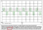
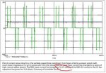
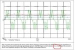
I was willing to define the conditions under which I did the test. I would have to write a special program and waste metal to put a full load on the motor. The only purpose of my test on some arbitrary real production machine (at the time this HAAS machine was built I believe their production was about 10,000 CNCs per year) was to look at the input current under 3 phase operation and see if the current was close to a sine wave. The waveform was nothing close to a sine wave.

I am willing to believe that some VFDs being built today have good (high, near unity) power factors. And we probably should be going in that direction, but show me their waveforms.

I agree. And data that I have run on my previously mentioned DC power supply provides some of this information. But since you do not believe that a large filter capacitor is an isolator, then it will be no proof to you. Waveforms and numeric measurements will follow at some time.

.
What it amounts to is we'll have to continue with our beliefs until we experience evidence to the contrary. :happyyes:
 

Smart $

Esteemed Member
Location
Ohio
Not so.
Do you want me to email you my spreadsheet?
Resubmit in report fashion. Assume we have no idea what that data means. I am able to interpret some of it. But I'm still at a loss for seeing input vs. output power factor.

If you're expecting me to do the math, you'll be waiting a long time. :happyyes:
 

gar

Senior Member
Location
Ann Arbor, Michigan
Occupation
EE
170619-1525 EDT

Smart $:

No surprise that the pulse you show in post #324 can have the same RMS value as the sine wave. However, I did not try to scale the plot and see if the values might correlate. How wide is the pulse?

.
 

Ingenieur

Senior Member
Location
Earth
In the model I previously referenced I can change the drive cap value (among many other values like diode characteristics, etc)
if I get motivated I may play with it and plot in/out pf
 

Smart $

Esteemed Member
Location
Ohio
170619-1525 EDT

Smart $:

No surprise that the pulse you show in post #324 can have the same RMS value as the sine wave. However, I did not try to scale the plot and see if the values might correlate. How wide is the pulse?

.
1/200th of a cycle in duration.
 

gar

Senior Member
Location
Ann Arbor, Michigan
Occupation
EE
170619-2000 EDT

Smart $:

It appears the RMS value of the sine wave is 1 major division. The peak of the pulse appears to be about 10 major divisions. I assume the pulse shape is rectangular. Using the same load resistance for both signals, and let the sine wave produce 1 unit of energy over 180 degrees.

Then we want 1 unit of energy over 180 deg for the pulse to have an equal RMS value. Square 10 which equals 100. To get the same 1 unit of energy the pulse needs to be 180/100 = 1.8 deg.

This correlates with your 1/200 of a full cycle.

.
 

Smart $

Esteemed Member
Location
Ohio
170619-2000 EDT

Smart $:

It appears the RMS value of the sine wave is 1 major division. The peak of the pulse appears to be about 10 major divisions. I assume the pulse shape is rectangular. Using the same load resistance for both signals, and let the sine wave produce 1 unit of energy over 180 degrees.

Then we want 1 unit of energy over 180 deg for the pulse to have an equal RMS value. Square 10 which equals 100. To get the same 1 unit of energy the pulse needs to be 180/100 = 1.8 deg.

This correlates with your 1/200 of a full cycle.

.
Exactly. However, it is a poor example for a high power factor. It calculates out to a veryry poor power factor. A great example would be a width of 180 degrees and peaks of 1 division... works out to a power factor of 1. Nonetheless, the point was to simply demonstrate a high power factor is not dependent on the current being sinusoidal.
 

GoldDigger

Moderator
Staff member
Location
Placerville, CA, USA
Occupation
Retired PV System Designer
Exactly. However, it is a poor example for a high power factor. It calculates out to a veryry poor power factor. A great example would be a width of 180 degrees and peaks of 1 division... works out to a power factor of 1. Nonetheless, the point was to simply demonstrate a high power factor is not dependent on the current being sinusoidal.
No, but it is more correlated with high power factor given that the voltage is known to be sinusoidal.

Sent from my XT1585 using Tapatalk
 

gar

Senior Member
Location
Ann Arbor, Michigan
Occupation
EE
170619-2400 EDT

Smart $:

Your have not proved what you claim.

Irms of a pulse of Ipeak = (Ton/Ttotal)^0.5

If we have a 0.1 ohm load (10 A when connected to a continuous 1 Vrms source), then the power dissipated in the load is 10 W (VA in this case).

If the on time of a constant DC (rectangular pulse) of 1 V to a 0.1 ohm load (10 A) is on for only 1/200 of a time period, then the average power is 0.05 W. Irms = 10*(1/200)^0.5 = 10*1/14.14 = 0.707 .

To verify Irms^2*0.1 = 0.05 W.

Power Factor = 0.05/10 = 0.005, not 1.

.
 

GoldDigger

Moderator
Staff member
Location
Placerville, CA, USA
Occupation
Retired PV System Designer
170619-2400 EDT

Smart $:

Your have not proved what you claim.

Irms of a pulse of Ipeak = (Ton/Ttotal)^0.5

If we have a 0.1 ohm load (10 A when connected to a continuous 1 Vrms source), then the power dissipated in the load is 10 W (VA in this case).

If the on time of a constant DC (rectangular pulse) of 1 V to a 0.1 ohm load (10 A) is on for only 1/200 of a time period, then the average power is 0.05 W. Irms = 10*(1/200)^0.5 = 10*1/14.14 = 0.707 .

To verify Irms^2*0.1 = 0.05 W.

Power Factor = 0.05/10 = 0.005, not 1.

.
I think that you are missing something, gar, although I am not going to point out your specific calculation error.

If I is at all times directly proportional to applied V, then it is a mathematical identity that P, the average of I(t)V(t) over time, must be exactly the product of Irms times Vrms. This holds true for any periodic waveform for which the RMS value is defined.

Sent from my XT1585 using Tapatalk
 

mike_kilroy

Senior Member
Location
United States
Forgetting the missing square math error, real world scope picture of AC input Irms for the same exact load power (so same avg input power in all 3 cases) shows the distortion PF issue in black and white. I posted this article back a ways, but here it is again. I stripped all the descriptions and just left the 3 scope pix here to make it easy to see. If these 3 different Irms values for same load don't make the different distortion PF clear, nothing will.


From https://www.motioncontrolonline.org...ng-Power-Factor-and-Harmonics/content_id/1545
 

Attachments

  • 1.jpg
    1.jpg
    26 KB · Views: 1
  • 2.jpg
    2.jpg
    25.1 KB · Views: 1
  • 3.jpg
    3.jpg
    25.2 KB · Views: 1

Smart $

Esteemed Member
Location
Ohio
170619-2400 EDT

Smart $:

Your have not proved what you claim.

Irms of a pulse of Ipeak = (Ton/Ttotal)^0.5

If we have a 0.1 ohm load (10 A when connected to a continuous 1 Vrms source), then the power dissipated in the load is 10 W (VA in this case).

If the on time of a constant DC (rectangular pulse) of 1 V to a 0.1 ohm load (10 A) is on for only 1/200 of a time period, then the average power is 0.05 W. Irms = 10*(1/200)^0.5 = 10*1/14.14 = 0.707 .

To verify Irms^2*0.1 = 0.05 W.

Power Factor = 0.05/10 = 0.005, not 1.

.
First off, I did not say when the pulses occur with respect to the voltage phase. It makes a huge difference in the result. :happyyes:

Works out to a power factor of about 0.14 if the pulses occur in phase with the voltage peaks.

Nonetheless, when you have a squared off waveform having 1A peaks, 180 degrees wide, we get a power factor of 1. My point was simply that a sinusoidal waveform is not required to achieve a high power factor.

From there, you should also make note that the intent of my generalized claim was simply that a VFD can improve power factor. I did not state the input of a VFD will have a high power factor for all motors at all percentages of loading.
 

gar

Senior Member
Location
Ann Arbor, Michigan
Occupation
EE
170620-0846 EDT

GoldDigger:

It should be self evidently clear that a resistive load continuously connected to any shape voltage source has a power factor of 1.

Switch that resistor on and off and view the switch and resistor as the load, then for any shape voltage source that is not identically matched to the switching in the load will have a power factor that does not equal 1.

It appeared from Smart $ waveform post that he was arguing that a short rectangular pulse load on a sine wave voltage source had a power factor of 1.

I think that Smart $ has been trying to argue that a load can have a good (near unity) power factor with a sine wave voltage source, normal AC power, where the load current is not close to a sine wave. In other words a diode rectifier with a large filter capacitor connected to its output.

.
 

gar

Senior Member
Location
Ann Arbor, Michigan
Occupation
EE
170620-0932 EDT

Smart $:

First off, I did not say when the pulses occur with respect to the voltage phase. It makes a huge difference in the result.
This is true. But you also have to define values, the load circuit, how the pulse width varies with position, and how pulse amplitude changes with position.


Works out to a power factor of about 0.14 if the pulses occur in phase with the voltage peaks.
How? What values are you using?

Assume your current pulse was 10 A and on time is 1/100, then Irms is 1 A. Assume 1 Vrms for voltage. Then Vrms*Arms = 1.

Average power is about 1.414*10/100 = 0.14, and PF = 0.14 so I assume these were your values.

Nonetheless, when you have a squared off waveform having 1A peaks, 180 degrees wide, we get a power factor of 1. My point was simply that a sinusoidal waveform is not required to achieve a high power factor.
We assume you are still using a voltage sine wave of 1.414 peaks, Vrms = 1 V. Since the current is constant in amplitude its Irms = 1 A. Thus, Vrms*Irms = 1.

However, average power is 1 (current) * 1.414 (peak voltage) * 0.636 (average value of a 1/2 cycle of a sine wave) = 0.899 . Thus, the power factor is about 0.9, not 1.

With a sine wave voltage source the load current must be a sine wave if the power factor is to be 1. In other words the load must be a continuously connecter resistor.

simply that a VFD can improve power factor
I don't think that is in dispute. But the power factor of a load on a DC supply with a large output capacitor does not reflect back thru the DC supply to be the power factor at the input to the DC supply. The power factor at the input to a DC supply is a function of the design of the power supply, and the load power (not factor) on the DC supply.

.


Status
Not open for further replies.
Top