Single Phase or Polyphase?

Status
Not open for further replies.

Hameedulla-Ekhlas

Senior Member
Location
AFG
for dot symbole and polartiy.

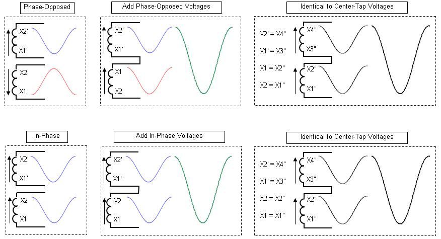
please the attached file.

The two black dots on the left-hand transformer indicate that at a certain time the current is coming "upward" out of both side. Since alternating current goes both "Up" and also "Down" a fraction of a second later it is pointless to say "+" or "-" and instead we describe the left hand transformer as "being in phase". In the right-hand transformer, the two coils are wound differently from each other so at any time when "positively" current is going "up" in the priamry coil, it is going "down" in the secondary. We describle this as "being 180 degree out of phase"

The black dots are only shown in those cases where this is an important item
 

jim dungar

Moderator
Staff member
Location
Wisconsin
Occupation
PE (Retired) - Power Systems
Both are valid reference frames but you are trying to say that only one frame is the "real" universal frame of reference and that all others are "math tricks".
I have not said only one thing is the real universe. I have said that a single center tapped winding is an additive connection.

You have one problem in that you think 120? is physically somehow treated different than 90? in that one angle means you have two phases while the other doesn't. I think you would eventually be able to work past that flaw in logic.
Wait a minute. where are angles of 120? and 90? coming from. I have been focusing my discussion on a single center tapped winding.

As for the phase-opposed case: It is going to come down to the wall I discussed many posts back that you will always hit. In order for you to hold your position, you must hold to the belief that when two voltages have a 180? phase difference, they must be the same phase. This position must be held while also saying that any other phase angle difference means they can be different phases.
What?
I have been saying it is possible to connect two single phase voltages in additive or subtractive series. If they are connected in additive (i.e. a single center tapped winding), then they should not be called 2-phase, even if the neutral is used as a reference.

I contend that this discontinuity in logic is what causes people to get confused when using the labels we have adopted. I think if people understand the physics of the situation, they can accept the labels, understand why we use them, and see that there is not really a discontinuity in logic.
I am arguing for using real world transformer (obeying Faraday and Lenz) connections of the voltages to describe if the system is (2) single phase sources or (1) 2-phase.

What we really have is a set of voltages that can be used for two different system configurations and we have made a preference choice on which name we will use.
If things change based on some as simple as if the neutral is used or not, then there is no single correct answer and you must include your reference point in your description such as: the (2) voltages appear to be out of phase only when the neutral is the reference.
 

mivey

Senior Member
I have not said only one thing is the real universe. I have said that a single center tapped winding is an additive connection.
You said (I think) that voltages with a phase angle displacement of 180? only appear to be out of phase
Wait a minute. where are angles of 120? and 90? coming from. I have been focusing my discussion on a single center tapped winding.
It goes to the point of using the common conductor in a phase count. You say two 120? displaced voltages with a common connection at the end point is single-phase but two 90? displaced voltages with a common connection at the end point is two-phase. It is the same logic that makes you say two 180? displaced voltages with a common connection at the end point is single-phase.
What?
I have been saying it is possible to connect two single phase voltages in additive or subtractive series. If they are connected in additive (i.e. a single center tapped winding), then they should not be called 2-phase, even if the neutral is used as a reference.
See previous response. I believe it covers what I understand to be your position. Feel free to clarify your position if I have misunderstood.
I am arguing for using real world transformer (obeying Faraday and Lenz) connections of the voltages to describe if the system is (2) single phase sources or (1) 2-phase.
And I am saying that regardless of how the voltages were created, they can be a source for more than one type system. I am focusing on the voltages and how they can be used, not how they were specifically derived. If they can be used as poly-phase voltages, then they can be a source for a system that needs poly-phase voltages.
If things change based on some as simple as if the neutral is used or not, then there is no single correct answer
That is correct. Technically, there is no single correct answer. The transformer can be used in more than one way. As part of our labeling process, we made a choice to pick only one of the usage options to define our label. As long as the user understands why we made the choice, the user does not make the assumption that the other usage options do not exist. The label we chose has some underlying assumptions that go along with it and is not completely descriptive of all the possible voltage configurations.
and you must include your reference point in your description such as: the (2) voltages appear to be out of phase only when the neutral is the reference.
They do not just appear to be, they are exactly the same voltages we get with a system that is out of phase. It just so happens that the two systems are twins. We are using the name from only one of the twins. It does not mean the other twin does not exist.
 

jim dungar

Moderator
Staff member
Location
Wisconsin
Occupation
PE (Retired) - Power Systems
You said (I think) that voltages with a phase angle displacement of 180? only appear to be out of phase.
No, I have said it is possible to connect voltages out-of-phase, but that does not make them 2-phase. This is why I have been adamant about focusing our discussion only to the actual physical construction of a single center tapped winding.

I explained, back in post #16
[quote = jim dungar]
My two waveform measurement possibilities are X1-X23 and X23-X4.
If X1 is our reference point, the two waveforms are seen as being in phase
If X23 is the reference, the two waveforms are seen as being 180? apart
If X4 is our reference point, the two waveforms are seen as being in phase[/quote]

If the voltages are physically connected in one manner, why is it incorrect to say they 'look different if you change the reference'?
 

mivey

Senior Member
No, I have said it is possible to connect voltages out-of-phase, but that does not make them 2-phase. This is why I have been adamant about focusing our discussion only to the actual physical construction of a single center tapped winding.
Then are you saying that two voltages with a 180? angle separation is never 2-phase? If so, you will always hit the wall I have discussed in the past. On the other hand, maybe your "no" just means two voltages on the same winding can't be voltages with a 180? angle separation. Either way, you are wrong because any discussion about a potential difference has no significance until you define the reference point. Using terminal numbers as a reference point is only one option, and does not represent the other options.
I explained, back in post #16
where you say that using any other reference point than the terminal numbers is sleight of hand
If the voltages are physically connected in one manner, why is it incorrect to say they 'look different if you change the reference'?
Because they are the same voltages you can get by adding two phase-opposed voltages. You continue to insist on using the terminal numbers as the universal designation of a reference point.

Source Case A: Take two independent in-phase voltages from 2-terminal transformers. To add them we connect X1-X2-X1'-X2'. Here you would promote the use of X1 as the reference or using the X1-X2 voltage as the reference.

Source Case B: Take two independent phase-opposed voltages from 2-terminal transformers. To add them we connect X2-X1-X1'-X2'. Here you would oppose the use of X1 as the reference and oppose the use of the X1-X2 voltage as the reference.

The center-tapped transformer can be used to supply the same voltages we get from either case. For the voltages we take from the transformer, we chose the label associated with case A but that does not mean Case B voltages are not able to be supplied from that same transformer.
 

jim dungar

Moderator
Staff member
Location
Wisconsin
Occupation
PE (Retired) - Power Systems
I have not been promoting one reference point over another. I have been saying that the 'number of phases' should not be dependent on which reference point is chosen.

My argument is, we should either add two voltages in series or subtract them, but the method should follow their real world connections and not depend on which measurement reference point is used.

I see too many instances where people try to troubleshoot or identify systems using only L-N or L-G voltages. They forget that there is not a single universal reference point.
 

mivey

Senior Member
I have not been promoting one reference point over another. I have been saying that the 'number of phases' should not be dependent on which reference point is chosen.
Again, discussion of a potential difference has no significance until a reference is chosen. The voltages are defined by the reference. There is no other way around it.

That is why I keep referring to the two-leg wye case. It is a clearer example of the dependence without the polarity confusion. With a line-line voltage, the only choice is single-phase. With line-neutral voltages, you have an option of two-phase voltages. This is no different than the end-connected 90 degree voltages yielding 2-phase voltages except for a slight difference in phase angles.

My argument is, we should either add two voltages in series or subtract them, but the method should follow their real world connections and not depend on which measurement reference point is used.
The sequence of the source terminal numbers does not dictate the sequence of the load terminal numbers. The method of derivation produces a set of voltages. It does not specify the exact manner in which we must use the voltages.

When you say we should use the transformer terminal numbers as a reference, you have made a reference choice but it is not the only valid reference choice. Look at case A & B from my previous post. These are real world voltages. These two different voltage systems just happen to map to the exact same set of voltages in this case. Because the mapping is identical, both sets of real world voltages can be provided by the center-tap transformer. We just traditionally use the label from one of the voltage sets.
I see too many instances where people try to troubleshoot or identify systems using only L-N or L-G voltages. They forget that there is not a single universal reference point.
They will eventually learn.
 

gar

Senior Member
Location
Ann Arbor, Michigan
Occupation
EE
100412-1013 EST

The word "phase" as used in AC electrical engineering is used to relate one point in a single waveform to another point in that same waveform, or the relation of one point on one waveform to an identical point on another waveform. Also there may be phase relationships between harmonically related waveforms.

One can read "waveform" to be voltage or current or something else. If we are talking about voltage, then there are two and only two points between which the voltage is measured. If you are concerned with voltage and more than two points, then there are multiple voltages and therefore multiple phases.

If we have two purely random noise sources, then we can not define a phase relationship between them because there is no common periodicity.

.
 

jim dungar

Moderator
Staff member
Location
Wisconsin
Occupation
PE (Retired) - Power Systems
When you say we should use the transformer terminal numbers as a reference, you have made a reference choice but it is not the only valid reference choice.

How is your use of use the neutral point, not using the terminal numbers as a reference?

A single center tapped winding, is physically (2) in-phase voltages connected additively in series.
 

mivey

Senior Member
How is your use of use the neutral point, not using the terminal numbers as a reference?
I am not restricting the use to just one terminal number sequence. I'm saying other terminal number sequences are valid options, not just a 1-2 and 3-4 sequence.

Case A uses 1-2 and 3-4 sequences (in-phase) and the 1-2 reference voltage is in phase with the 3-4 voltage.

Case B uses 2-1 and 3-4 sequences (phase-opposed) and the 2-1 reference voltage is in phase-opposition with the 3-4 voltage.

In your case, you say we must use the terminals as they are numbered or we do not have real voltages. I do not agree as the voltages are defined by the reference we choose. Both options yield real, valid voltages.

A single center tapped winding, is physically (2) in-phase voltages connected additively in series.
That describes the derivation method using the line-side voltage as a reference frame. The voltages we obtain can be used physically as two in-phase voltages added or two opposed-phase voltages added. They are the exact same voltages. The difference is the load-side reference frame.
 

mivey

Senior Member
100412-1013 EST

The word "phase" as used in AC electrical engineering is used to relate one point in a single waveform to another point in that same waveform, or the relation of one point on one waveform to an identical point on another waveform. Also there may be phase relationships between harmonically related waveforms.

One can read "waveform" to be voltage or current or something else. If we are talking about voltage, then there are two and only two points between which the voltage is measured. If you are concerned with voltage and more than two points, then there are multiple voltages and therefore multiple phases.

If we have two purely random noise sources, then we can not define a phase relationship between them because there is no common periodicity.

.
Thanks for the reminder. And as a refresher:

Even with a 1-2 & 3-4 sequence, we have two phases. However, these can't be grouped into a single poly-phase system because they have the same phase angle. They remain classified in separate single-phase systems.

With a 2-1 & 3-4 sequence, we also have two phases. But, these can be grouped into a single poly-phase system because they have different phase angles. They can become part of a 2-phase system when used together or remain in separate single-phase systems when used separately.

In either case, adding the two phases produces a larger voltage that is classified in a single-phase system by itself.
 

jim dungar

Moderator
Staff member
Location
Wisconsin
Occupation
PE (Retired) - Power Systems
Even with a 1-2 & 3-4 sequence, we have two phases. However, these can't be grouped into a single poly-phase system because they have the same phase angle. They remain classified in separate single-phase systems.
Aren't you now saying that (2) in-phase voltages added together cannot be considered 2-phase?
 

mivey

Senior Member
Aren't you now saying that (2) in-phase voltages added together cannot be considered 2-phase?
I have never said two in-phase voltages would be included in a two-phase system. I have said they could be in two separate single-phase systems.

Added together, I have always said the sum of the two voltages is a different phase. In a system of phases, the voltage magnitudes must be the same and the phase angles different.
 

jim dungar

Moderator
Staff member
Location
Wisconsin
Occupation
PE (Retired) - Power Systems
I have never said two in-phase voltages would be included in a two-phase system. I have said they could be in two separate single-phase systems.
So you are saying, if the (2) voltages are actually in-phase the choice of the reference point cannot change them into 2-phase.
 

mivey

Senior Member
So you are saying, if the (2) voltages are actually in-phase the choice of the reference point cannot change them into 2-phase.
If you choose a reference point that makes them in phase, you can't use another reference point at the same time that makes them out of phase. Only one reference point per turn please.
 

LarryFine

Master Electrician Electric Contractor Richmond VA
Location
Henrico County, VA
Occupation
Electrical Contractor
Case A uses 1-2 and 3-4 sequences (in-phase) and the 1-2 reference voltage is in phase with the 3-4 voltage.

Case B uses 2-1 and 3-4 sequences (phase-opposed) and the 2-1 reference voltage is in phase-opposition with the 3-4 voltage.
But, you can not create Case B from a single, center-tapped secondary.

Both options yield real, valid voltages.
How would you get 240v from Case B?
 

mivey

Senior Member
But, you can not create Case B from a single, center-tapped secondary.
Of course you can. The voltages are the same. The difference is in what the terminals represent from the original case.
How would you get 240v from Case B?
By adding the phases. The only difference is what you choose as the reference. In the in-phase case, the original reference "X1" terminal is represented by the end of the center-tap winding. In the opposed-phase case, the original reference "X1" terminal is represented by the mid-point of the center-tap winding. These are real voltages, not mathmatical models. You can use a function generator and some transformers and see the physical results. See graphic.

AddingVoltagesInandOutofPhase.jpg


Let's call the voltage a force for a moment. For phase opposition, we could just use two phase-opposed forces without going through a transformer. If we want to scale the forces, we can send them through separate single-phase transformers. We can even use one single-phase transformer to accomplish the task.

The catch in using a single-phase transformer to combine phase-opposed forces is that we have to align them so their fluxes will couple together and flow as a single flux through the single core, otherwise they will just cancel each other. Once on the load side, we can separate the forces by using the center-tap. These forces are separate and we can feed separate loads or even send them through isolation transformers to separate them from the center-tap winding and separately ground them any way we please.

With a single line-side force that is twice the value of the individual forces discussed before, we can again create two separate forces on the load side of the single-phase transformer. That is why I say the method of derivation is not the issue. The issue is what forces we can create on the load side. If we can use the transformer to create the same forces we could get by using two phase-opposed forces without transformers, then the transformer can be a source for phase-opposed forces.
 

jim dungar

Moderator
Staff member
Location
Wisconsin
Occupation
PE (Retired) - Power Systems
In your examples you are never creating a 'phase-opposed' connection.

1) You inverted one of the voltages so that it is now in phase with the other voltage.
2) Then you added them while still calling them 'phase-opposed'.

No wonder, you don't want to describe the number of phases by their actual physical connection.
 

mivey

Senior Member
In your examples you are never creating a 'phase-opposed' connection.

1) You inverted one of the voltages so that it is now in phase with the other voltage.
2) Then you added them while still calling them 'phase-opposed'.

No wonder, you don't want to describe the number of phases by their actual physical connection.
If you do not understand that the voltage from X1 to X2 in the phase-opposed case is 180 degrees out of phase with the voltage from X1' to X2' then it is no small wonder that you struggle with voltage references.

If we have two in-phase voltages with instantaneous values +1 and +1, we can "add" them to get 2 volts (X1-X2-X1'-X2'). If we want the 2 volts with phase-opposed voltages with instantaneous values of +1 and -1, we have to "subtract" them. "Subtraction" is done by connecting the leads the other way (X2-X1-X1'-X2'). The reverse combinations for the two cases would yield zero volts. But I think you already knew all of this.
 

jim dungar

Moderator
Staff member
Location
Wisconsin
Occupation
PE (Retired) - Power Systems
If you do not understand that the voltage from X1 to X2 in the phase-opposed case is 180 degrees out of phase with the voltage from X1' to X2' then it is no small wonder that you struggle with voltage references.
Have you devolved into personal attacks?

mivey said:
If we have two in-phase voltages with instantaneous values +1 and +1, we can "add" them to get 2 volts (X1-X2-X1'-X2'). If we want the 2 volts with phase-opposed voltages with instantaneous values of +1 and -1, we have to "subtract" them. "Subtraction" is done by connecting the leads the other way (X2-X1-X1'-X2'). The reverse combinations for the two cases would yield zero volts. But I think you already knew all of this.

You admit that 'phase-opposed' voltages can not be directly connected, your drawings clearly indicate you are actually adding the opposite of your 'phase-opposed' voltage. This contradicts what you have said in previous posts.

mivey said:
Post 147
There is nothing that says we can't use the two 120 volt sources together in phase opposition to supply two phases to a two-phase load.

Post 157
The voltages not only appear to be out of phase, they really are out of phase if wired that way.


But you say I am wrong for wanting to describe the number of phases based on the actual connections of the voltages.
 
Status
Not open for further replies.
Top