Single Phase vs Three Phase flow of electrons with no neutral/grounded path?

Status
Not open for further replies.

ggunn

PE (Electrical), NABCEP certified
Location
Austin, TX, USA
Occupation
Electrical Engineer - Photovoltaic Systems
I'm guessing he was careful, as he saw it was melted and assumed current flow.

He did say he got shocked on the metal frame door when he tried to enter the house.
In a related story...

In a rent house I used to live in, there was a window with an aluminum frame in the shower. I learned very quickly not to touch that windowframe while I was in the shower. That was before I knew much about electricity, but I did measure 120V between the windowframe and the drain in the shower. It was a high impedance path and there wasn't enough current available for an electrocution, obviously, since I am writing this, but enough for an unpleasant jolt.
 

Besoeker

Senior Member
Location
UK
3. Three phase originates in and is ideally suited for rotating machinery, motors and generators.
Three phase transmission and distribution also benefits from the reduction in conductor material and thus cost. I have a notion that this may have been one of the main factors in its adoption.

In a two pole rotating machine, the armature is a North to South constant bar magnet and it sweeps past the A, B, C field coil pairs, generating a sinewave voltage in the field coils. The A, B, C field coils are physically seperated by place and so also seperated by time, as the rotating armature magnetic field induces voltage sequentially, in the A field coil, then the B field coil, then C, then A again.
That would be dependent of the type of machine.
For a cage induction machine, the rotating field is in the stator. The rotating field induces current in the rotor bars resulting torque.

Nice cut and paste job with the equations, BTW.

[/QUOTE]
 

EEC

Senior Member
Location
Maryland
I am trying again

I am trying again

Ok, single phase is created by one high voltage alternating phase from PCO supplying a single phase transformer. There is one alternating current sine wave input to primary side of transformer. When primary sine wave is above the reference 0, one secondary output (115V) is above reference 0 also. The other secondary sine wave output (115V) is below reference 0. By reference I mean when there is no current or voltage showing on the sine wave.

What?s different when two phases from a three phase 208/120V system supply a 208V load?
 

david luchini

Moderator
Staff member
Location
Connecticut
Occupation
Engineer
Ok, single phase is created by one high voltage alternating phase from PCO supplying a single phase transformer. There is one alternating current sine wave input to primary side of transformer. When primary sine wave is above the reference 0, one secondary output (115V) is above reference 0 also. The other secondary sine wave output (115V) is below reference 0. By reference I mean when there is no current or voltage showing on the sine wave.

What?s different when two phases from a three phase 208/120V system supply a 208V load?

Nothings different...Lets try it this way. If you have a 230/115V single phase system that is the secondary of a single phase transformer, you have two secondary windings each of which is rated at 115V, connected together at a common point, the neutral. You seem clear that the two windings phase angles are 180 degrees separated. So you have V1=115Volts at angle 0 (115V<0) and V2=115 at angle 180 (115V<180). If you connect a load between V1 and V2, then the voltage across the load (VL) would be equal to V1-V2. So VL=V1-V2, or VL=(115<0)-(115<180). Using vector addition the result is VL=(115<0)-(115<180)= 230<0. If think you are clear on this result. The resulting voltage across a load connected from V1 to V2 is 230V.

Now lets consider a 208/120V three phase system that is the secondary of a three phase transformer. We now have 3 line to neutral voltages which are separated by 120 degrees phase angle. So, V1=120V<0, V2=120<120 and V3=120<240. If you connect a load between V1 and V2, then the voltage across the load (VL) is still equal to V1-V2. So VL=V1-V2, or VL=(120<0)-(120<120). Using vector addition, the result is VL=208<-30. So the resulting voltage across a load connect from V1 to V2 is 208V.

Connecting across the two legs of a single phase system, or across two legs of a three phase system is the same. The voltage across the load is calculated the same way (V1-V2). But because the phase angle separation is different, the single phase system produces a voltage which is 2 times the line-to-neutral voltage, and the three phase system produces a voltage which is 1.732 times the line-to-neutral voltage.
 

Smart $

Esteemed Member
Location
Ohio
...

What’s different when two phases from a three phase 208/120V system supply a 208V load?
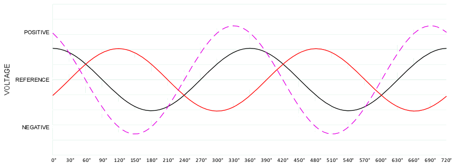
The voltage angles (degrees out of phase). Refer to following diagram:

120-2081waveform.gif


Black line measured neutral (negative/common lead) to L1 or A (positive lead).
Red line measured neutral (negative/common lead) to L2 or B (positive lead).
Magenta line measured L2/B (negative/common lead) to L1/A (positive lead).

Note the voltage difference between black and red lines at various points in time (given in degrees). Compare to voltage difference between Reference and magenta line.
 
Last edited:

Besoeker

Senior Member
Location
UK
The voltage angles (degrees out of phase). Refer to following diagram:
Black line measured neutral (negative/common lead)
It's a 208V load fed by a 208V supply.
It is a line to line single phase supply.
Neutral doesn't come into it. Phase displacement from line to neutral is irrelevant.
 

Smart $

Esteemed Member
Location
Ohio
It's a 208V load fed by a 208V supply.
It is a line to line single phase supply.
Neutral doesn't come into it. Phase displacement from line to neutral is irrelevant.
True. But the question was what is different [implied: 208/120V vs. 120/240V supplies]. And my answer establishes why the voltage is 208V instead 240V, which I believe a necessary inclusion considering the discussion thus far.
 

Besoeker

Senior Member
Location
UK
True. But the question was what is different [implied: 208/120V vs. 120/240V supplies]. And my answer establishes why the voltage is 208V instead 240V, which I believe a necessary inclusion considering the discussion thus far.
I disagree. The 208V supply is two just two conductors. It's single-phase. That's all there is to it.
 

david luchini

Moderator
Staff member
Location
Connecticut
Occupation
Engineer
I'll take the over on 314 posts on this one.

Chris, we got long way to go on this one.

I disagree. The 208V supply is two just two conductors. It's single-phase. That's all there is to it.

Yes, the 208V supply is just two conductors and it is just single phase. But the OP is clearly having difficulty with that. To say "that's all there is to it" isn't going to help alleviate the poster's confusion.
 
Location
Ohio
I disagree. The 208V supply is two just two conductors. It's single-phase. That's all there is to it.

Maybe you could explain this further?

Showing voltage difference L-N and L-L, then showing phase offset is exactly what is different between a 240/120 and a 208/120 system.

No one's saying that we're USING a neutral wire, he's simply showing the voltage difference to help explain OP's question.

240V = 2 wire, 180deg phase difference.
208V = 2 wire, 60deg phase difference.
 

Besoeker

Senior Member
Location
UK
Maybe you could explain this further?

Showing voltage difference L-N and L-L, then showing phase offset is exactly what is different between a 240/120 and a 208/120 system.

No one's saying that we're USING a neutral wire, he's simply showing the voltage difference to help explain OP's question.

240V = 2 wire, 180deg phase difference.
208V = 2 wire, 60deg phase difference.
The 240V 2-wire is a single phase voltage obtained end to end of of a transformer winding that has a winding with a center tap. If the center tap isn't connected to the load it plays no part (obviously) so the fact that the two ends of the winding are in anti-phase with respect to the center tap isn't relevant - it would make no difference if it wasn't there.
The 208V 2-wire is also single phase. As I posted earlier, there can be no phase shift between voltages if there is only one phase.
 

Besoeker

Senior Member
Location
UK
Yes, the 208V supply is just two conductors and it is just single phase. But the OP is clearly having difficulty with that. To say "that's all there is to it" isn't going to help alleviate the poster's confusion.

Not sure that introducing phase shifts that don't exist offers greater clarification.
 

david luchini

Moderator
Staff member
Location
Connecticut
Occupation
Engineer
there can be no phase shift between voltages if there is only one phase.

That's great, but the system is question is 3 phase. How does a 3 phase system have only 1 phase?

Not sure that introducing phase shifts that don't exist offers greater clarification.

I'm not introducing phase shifts that don't exist. The phase shifts exist because the system is a 208/120V, 3 phase wye. If the system source was a generator or a transformer secondary, the voltage developed on each of the 3 windings of the source is 120V. The 120V voltage on each of the 3 source windings have 120 degree phase shifts.

If I connect a load across two of the source terminals, L1 and L2, then KVL tells me that the voltage across the load will equal the voltage across winding 1 minus the voltage across winding 2.

Vl=V1-V2 = (120<0)-(120<-120) = 208<-30. The 120 degree phase shift between the two 120V source windings is precisely why the voltage between the terminals L1 and L2 is 208V.
 

skeshesh

Senior Member
Location
Los Angeles, Ca
David, I think what Besoeker is trying to dispel is that the OP seems to think there are two waveforms with a phase shift when a L-L connection is made. Of course you're vector sum is correct and the 208V@30deg results from 120@0deg and 120@120deg, but I dont think Besoeker was trying to disagree with that.
 

david luchini

Moderator
Staff member
Location
Connecticut
Occupation
Engineer
David, I think what Besoeker is trying to dispel is that the OP seems to think there are two waveforms with a phase shift when a L-L connection is made. Of course you're vector sum is correct and the 208V@30deg results from 120@0deg and 120@120deg, but I dont think Besoeker was trying to disagree with that.

It is clear that the OP seems to think that there are two waveforms. I've been trying to dispel that notion in my responses to his questions. Simply saying "its just single phase" isn't going to clarify the situation for the OP. If the OP grasped the concept that "its just single phase," he wouldn't be asking the questions he's asking. The point is to try to get the OP to understand why the connection between the two lines of a three phase system supplies "just single phase."
 
Last edited:
Status
Not open for further replies.
Top