single vs. 3 phase

Status
Not open for further replies.

jim dungar

Moderator
Staff member
Location
Wisconsin
Occupation
PE (Retired) - Power Systems
rattus said:
We change from KVL to KCL.
Isn't the math still the same? Are you saying we need to change your method from KVL to KCL?

I have not been involved in discussing the math of vectors, I have been asking for reasons to follow your single phase voltage direction convention (which ignores physical connections), or reasons not to follow mine (which follows physical connections just like I do for 3-phase).
 

rattus

Senior Member
jim dungar said:
The legs are not actually 180 degrees apart. They appear to be 180 degrees apart only when measured using the neutral as a reference point.

Jim, the quote above is the only disagreement. The OP was clearly referring to the voltages on L1 and L2 relative to N. These voltages, as defined, not only appear to be 180 degrees out of phase, they are. Really.

To prove it, let us call the CT of a 4-wire delta, "G". Now add the phasors around the loop.

Vag = 120V @ 0
Vbg = 208V @ 90
Vcg = 120V @ 180

The way you arrange your sources does not change this basic fact. That is all there is to it. Really.
 

mivey

Senior Member
Jim, Thanks for the feedback.

jim dungar said:
Excellent references, but this just is a personal opinion
No doubt. But is a personal opinion shared by many, in no small number.
jim dungar said:
...The author constantly points out why polarity dots are important...
I thought the auther made a distinction between polarity dots (the "polarity markings" on a transformer) and the polarity marks (+ - symbols) used to define the frame of reference. It appears the author says the polarity dots (markings) are used to establish the relationship between two different voltage sources.

The author also shows that the polarity "marks" do not necessarily have to match the polarity "dots" (like in a split-phase) because you can use the + - polarity marks to establish the frame of reference you decide to use. The diagrams shown in Vol 2, Chapt 10/2 show this in the discussion of split-phase power systems.
jim dungar said:
...I believe that rattus prefers to use an unconventional method as described in Chapter 2/7.
I believe the author only called it unconventional in Vol 2, Chapter 2/7 when talking about a battery source, not an AC source.

Maybe the problem is that I see the polarity dots as a description of the wiring and of how the wires come out of a transformer. I did not think that the way it was wired forced me to define my reference in a particular way.

For yet another center-tap/neutral reference example, doesn't Article 647 describe a system with a center-tap reference and two 60 volt lines of opposite polarity?
 

jim dungar

Moderator
Staff member
Location
Wisconsin
Occupation
PE (Retired) - Power Systems
rattus said:
...voltages, as defined, not only appear to be 180 degrees out of phase, they are. Really.
I have not been arguing that V1n is in phase with V2n. I have been saying that it is key that you include your definition it should not be assumed. I have been saying that this method of choosing sources has issues which may make it inappropriate for common use and it is not consistent with the real world which why I say 120/240 is two 120V sources in series (hmmm maybe I need to change this to additive series).

rattus said:
The way you arrange your sources does not change this basic fact. That is all there is to it. Really.
So are you saying, choosing the source direction is not important and the only fact is that V = -(-V)?

For a 4-wire delta, I would not pick my voltages as Vag and Vcg as these do not follow the way the windings are actually built. I would not evaluate Vbg. All of my vectors would be connected head to tail just like when I do a 3-wire delta.
 

mivey

Senior Member
jim dungar said:
For a 4-wire delta, I would not pick my voltages as Vag and Vcg as these do not follow the way the windings are actually built. I would not evaluate Vbg. All of my vectors would be connected head to tail just like when I do a 3-wire delta.
But isn't a reference to ground what is done with metering, like a form 9S or 9A meter, and don't the phasors for these metered values point away from the neutral?

[edit: typo]
 
Last edited:

rattus

Senior Member
jim dungar said:
I have not been arguing that V1n is in phase with V2n. I have been saying that it is key that you include your definition it should not be assumed.
But Jim, the OP made that clear, and the 'n' subscript makes that clear.
have been saying that this method of choosing sources has issues which may make it inappropriate for common use and it is not consistent with the real world which why I say 120/240 is two 120V sources in series (hmmm maybe I need to change this to additive series).
But, no one, certainly not I, has said that it was. The only issue is your statement to the OP which I felt was misleading and confusing.
So are you saying, choosing the source direction is not important and the only fact is that V = -(-V)?
I am saying the Vcg is 120V @ 180 degrees, and that fact cannot be changed. Either way, the results come out the same.
For a 4-wire delta, I would not pick my voltages as Vag and Vcg as these do not follow the way the windings are actually built. I would not evaluate Vbg. All of my vectors would be connected head to tail just like when I do a 3-wire delta.
That is a perfectly valid approach, but does not change the phase relationships.
 

coulter

Senior Member
rattus said:
Carl, explain to me what rotates in an open wye. I can't see this at all.
Since you and mivey have both chewed me out for being too complex - I'll keep this simple.

Hook the three leads of a 208 open Y to a 3ph motor and it will turn. Hook the three leads of a single 120/240up to a three phase motor and it will .... you guess. (No fair giving the motor a flip to get it started)

I've never tried this, so if someone who understood the physics wanted to tell me I was all was all wet, I'd believe them.

mivey said:
... I contend that I can define a reference point for the 240 that will show that V1 and V2 rotate. ...
Okay - show me this one. For credit, tell where this would actually be used in this universe.

mivey said:
The crux of the matter is the reference point. ... With the 208 wye, I could also draw a line between V1 and V2 and use the midpoint as a reference and claim they do not rotate.
Huh? Draw that one out. show where the three leads coming from the supply connect. Again, fFor credit, tell where this would actually be used in this universe.

carl
 

mivey

Senior Member
coulter said:
Since you and mivey have both chewed me out for being too complex
Did I do that? I don't remember. With all the fun we have been having I must have forgotten.
coulter said:
I'll keep this simple.
Good. I get confused when I get confused.
coulter said:
Okay - show me this one. For credit, tell where this would actually be used in this universe.
The reference point for the 240 could be the neutral point of the delta. It could also be the 3rd line conductor of the delta. The point was that the mid-coil reference point made it look like they were not rotating. If you move the reference point, you can see a rotation. I guess you could shift the reference point if you wanted to turn a motor, but I would have to ask one of our resident motor experts.
coulter said:
Huh? Draw that one out. show where the three leads coming from the supply connect. Again, fFor credit, tell where this would actually be used in this universe
Draw a mental picture from the following: Only the two line conductors would be used. They would connect to a center-tapped transformer. As for use, this center-tapped transformer could use the center tap as a reference and you would have a split-phase system where balanced resistive loads yield a net zero neutral current.

[edit: I'm not sure but does a static phase converter "create" some kind of rotational set of voltages so you can run 3 phase equipment on a single phase source? I'm not sure but it seems like I read some stuff on a static phase converter years ago and it kind of sounded like it]
 
Last edited:

rattus

Senior Member
Yes, but?

Yes, but?

coulter said:
Hook the three leads of a 208 open Y to a 3ph motor and it will turn. Hook the three leads of a single 120/240up to a three phase motor and it will .... you guess. (No fair giving the motor a flip to get it started)
I believe a 3-phase motor would start and run on 2 phases, but what does that have to do with with the choice of reference or the phasor diagrams for that matter?
 

jim dungar

Moderator
Staff member
Location
Wisconsin
Occupation
PE (Retired) - Power Systems
mivey said:
But isn't a reference to ground what is done with metering, like a form 9S or 9A meter, and don't the phasors for these metered values point away from the neutral?

The vectors point in the direction of the polarity marks of the transformer windings. A center-tapped winding only has one polarity dot so all vectors point in the same direction.
 

jim dungar

Moderator
Staff member
Location
Wisconsin
Occupation
PE (Retired) - Power Systems
mivey said:
The author also shows that the polarity "marks" do not necessarily have to match the polarity "dots" (like in a split-phase) because you can use the + - polarity marks to establish the frame of reference you decide to use. The diagrams shown in Vol 2, Chapt 10/2 show this in the discussion of split-phase power systems.I believe the author only called it unconventional in Vol 2, Chapter 2/7 when talking about a battery source, not an AC source.

I have said the polarity marks are important when choosing the direction of the source.

In chapter 2/7 the author says:
The polarity markings show these two voltage sources aiding each other, so to determine the total voltage across the resistor we must add the voltage ? together to obtain ?


Please note that the authors polarity marks match those of rattus?s previous diagrams but the author says we add in this situation and rattus says we subtract.

But the author says it is
? perfectly acceptable to represent the 6 volt source ? with a reversed set of polarity markings, and still arrive at the same total voltage.

Again rattus says we do not need to follow the polarity marks.

The author supports my view that the real world connection is important
Therefore, any polarity marks must be included as additional symbols on the diagram, and there is no one ?correct? way in which to place them. They must, however, correlate with the given phase angle to represent the true phase relationship of that voltage with other voltages in the circuit


In chapter 10.1 the drawings for the "split-phase" circuit show the polarity marks of the sources opposite thos that rattus uses.
 

coulter

Senior Member
rattus said:
I believe a 3-phase motor would start and run on 2 phases ...
It won't start. If running, it will stay running until the overloads take it out.

rattus said:
... but what does that have to do with with the choice of reference ...
I don't know - you would have to talk to mivey about that.

rattus said:
... but what does that have to do with ... the phasor diagrams for that matter?
I thionk that is already answered. Could be you would have to actually read my posts and make an attempt to understand.

carl
 

mivey

Senior Member
jim dungar said:
The vectors point in the direction of the polarity marks of the transformer windings. A center-tapped winding only has one polarity dot so all vectors point in the same direction.
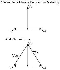
Not sure I understand what you mean. As I understand it, the phasors for the 4 wire delta metering would be in the directions as shown in the top picture here and would not all be pointing in the same direction:
DeltaPhasors2.jpg
 

coulter

Senior Member
mivey -

I think what we have here is a failure to communicate - possibly on more that one level.

mivey said:
....The reference point for the 240 could be the neutral point of the delta. It could also be the 3rd line conductor of the delta. ...
Look at posts 209 and 225. 120/240 refers to single phase, not a delta - that would be refered to as 240/120. See NEMA C84.1. My comment is based on single phase.

mivey said:
... Draw a mental picture from the following: Only the two line conductors would be used. They would connect to a center-tapped transformer. ...
My comment refers to 208 open Y. Yes, you can make it look like it does not rotate if you ignore a piece of the system. Try this again using all of the 208 open Y. My point is the system as a whole does not rotate.

Using your logic, a 480/277 Y can be shown to not rotate by picking the appropriate reference. How is that he asks? Well, I'm only going to use one 277V leg to neutral and connect the two leads to a CT xfm. Now that doesn't make any sense at all.

Perhaps we had another failure to communicate.

mivey said:
... I'm not sure but does a static phase converter "create" some kind of rotational set of voltages so you can run 3 phase equipment on a single phase source?
Oh yeah, that's exactly what it does - Creats a phase shifted third phase.

carl
 

coulter

Senior Member
mivey said:
Not sure I understand what you mean. As I understand it, the phasors for the 4 wire delta metering would be in the directions as shown in the top picture here and would not all be pointing in the same direction:
DeltaPhasors2.jpg

mivey -
Isn't your first picture a 4W Scott Tee. Usually there is an N connection a little ways up the Vc vector. I've never seen Scott Tee connections refered to as 4W Delta.

edited for some clarity (I hope)

carl
 

mivey

Senior Member
jim dungar said:
...In chapter 10.1 the drawings for the "split-phase" circuit show the polarity marks of the sources opposite thos that rattus uses.
Then I have been completely off base with regards to that. I must have overlooked something in the past because I thought rattus was supporting the following drawing from chapter 10.1:
Vol2Chpt10_1diagram.jpg
 

mivey

Senior Member
coulter said:
mivey -
Isn't your first picture a 4W Scott Tee. Usually there is an N connection a little ways up the Vc vector. I've never seen Scott Tee connections refered to as 4W Delta.

edited for some clarity (I hope)

carl
It is a phasor diagram, not a circuit diagram. The "N" point is where the dot is at at the tails of Va & Vb. I might should have labeled them Van, Vbn, and Vcn.
 

coulter

Senior Member
educate carl question:

I read mivey's references. The author refers to a 120/240 single phase as "split phase". I have not heard of that before. Is this common in the single phase end of the trade?

Is there any application of this term, "split phase" to Wye three phase system? How about 240/120 D systems?

I have heard of, "split phase" in conjunction with a particular type of construction for single phase motors - can't say I know what it is (they are?). I don't know too much about single phase motors. And I don't know if this has anything to do with the reference author's comments.

color me in a quandry

carl
 

jim dungar

Moderator
Staff member
Location
Wisconsin
Occupation
PE (Retired) - Power Systems
mivey said:
Not sure I understand what you mean. As I understand it, the phasors for the 4 wire delta metering would be in the directions as shown in the top picture here and would not all be pointing in the same direction:
DeltaPhasors2.jpg

Start with the vectors for a 3-wire delta.
Now without adding any connections simply identify a tap location at the 57.7% point of each Line-Line voltage (remember this is still a 3-wire circuit). What do you need to change about your vectors and why?
 

coulter

Senior Member
mivey said:
It is a phasor diagram, not a circuit diagram. The "N" point is where the dot is at at the tails of Va & Vb. I might should have labeled them Van, Vbn, and Vcn.
I don't mind the drawing not having a "N". Scott Tee connections don't always have neutral. So, tell me a little more.

How would you draw the vector diagram for a Scott Tee that did not have a neutral?

How would that be different from door #1?

carl
 
Status
Not open for further replies.
Top