single vs. 3 phase

Status
Not open for further replies.

crossman

Senior Member
Location
Southeast Texas
As for the motors... I just did these experiments in the lab:

Given:

1/4 hp, 3-phase squirrel-cage, induction motor with no mechanical load
208Y/120 3-phase, 4-wire power source
120/240 single-phase power source

Note: any reference to speed is speculation from the observable data.

Experiment A: 208Y/120 A, B, and C connected to motor = motor starts and runs

Experiment B: 208Y/120 Only A and B connected to motor, C phase not connected = motor does not start, just hums. (Motor will run if I give the rotor a spin by hand, but it is obviously not running efficiently or at full speed)

Experiment C: 208Y/120 A, B, and N connected to motor = motor starts and runs, but not quite at full speed compared to A, B, and C connection

Experiment D: 120/240 single phase A, B connected to motor = motor does not start, just hums. (Motor will run if I give the rotor a spin by hand, but it is obviously not running efficiently or at full speed)

Experiment E: 120/240 single phase A, B, and N connected to motor = motor does not start, just hums. (Motor will run if I give the rotor a spin by hand, but it is obviously not running efficiently or at full speed)

This is all as expected from the theory of the situations.
 

mivey

Senior Member
coulter said:
I think what we have here is a failure to communicate - possibly on more that one level...
Could be. I'll tell you my logic and you can "Spock" it out to see if it makes sense.

For the center tapped leg of the delta, the two line conductors are still part of the 3 phase system. If you are saying the line voltages at the center tapped coil are not rotating, I would call that a failing of logic because all we have done is ignore/not use the 3rd line conductor in the delta.

The same logic failing would apply to the two line conductors of the wye. If I could put a center-tapped coil between the line conductors, and use the center of this coil as a reference, that does not mean the line conductors are no longer rotating when referencing the original neutral reference.
coulter said:
educate carl question..."split phase"....Is this common in the single phase end of the trade?...I have heard of, "split phase" in conjunction with a particular type of construction for single phase motors...
It is commonly used. I would not call it the best terminology, but such is our industry. It does cause confusion because the more common use is for the split-phase motor. I'm not motor expert but it has to do with having two unlike windings that "split" or create a phase displacement at startup so the motor will rotate with a single-phase source.

As for wye use, you could put a transformer across the 208 legs to get a center-tapped source for feeding a power supply, but I can't think of where one is used as I would think most of them would just rectify the L-L voltage. Maybe someone else has knowledge in this area.
 

crossman

Senior Member
Location
Southeast Texas
As for the split-phase motor, it has a "run" winding and a "start" winding connected in parallel. These two windings have different inductive reactances and resistances, and therefore the currents in the two windings will be out of phase, typically 20 to 30 degrees. Hence, "split-phase". After the motor is started, a centrifugal switch disconnects the start winding because the 20 to 30 degrees is not enough phase difference to "keep up with" the speed of the rotor.

As for calling anything else "split-phase", personally I have not heard of that.
 

coulter

Senior Member
mivey said:
... For the center tapped leg of the delta, the two line conductors are still part of the 3 phase system. If you are saying the line voltages at the center tapped coil are not rotating, I would call that a failing of logic because all we have done is ignore/not use the 3rd line conductor in the delta. ...
For this example, I'm discussing 120/240 single phase - nothing to do with 240/120D. If I am understanding you correctly, we're not on the same subject. I repeat, look at posts 209 and 225. 120/240 single phase - no 3ph in this picture.

added note: You're right - if one adds the third phase turning the system into a Scott Tee, it rotates. But I'm not adding anything here just like I'm not ignoring part of the 208 open Y in the nest segment.

mivey said:
... The same logic failing would apply to the two line conductors of the wye. If I could put a center-tapped coil between the line conductors, and use the center of this coil as a reference, that does not mean the line conductors are no longer rotating when referencing the original neutral reference. ...
I repeat: Yes, if one chooses to ignore part of the system, it doesn't rotate. Again, I'm asking, please read posts 209 and 225. I'm using all three wires.

I'm lost on where the missed communication is coming from - why you are adding extra phases to get single phase to rotate eludes me.

carl
 

coulter

Senior Member
mivey said:
... It is commonly used. I would not call it the best terminology, but such is our industry. It does cause confusion because the more common use is for the split-phase motor. ...
Where else (besides your noted references) have you heard of the term, "split phase", for referencing a 120/240 single phase? Any other references - old timers way back when?

I'm curious where this comes from.

carl
 

mivey

Senior Member
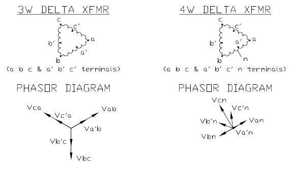
I'm turning in my homework

I'm turning in my homework

jim dungar said:
Start with the vectors for a 3-wire delta.
Now without adding any connections simply identify a tap location at the 57.7% point of each Line-Line voltage (remember this is still a 3-wire circuit). What do you need to change about your vectors and why?
Ok I added the taps for the 3 wire and 4 wire delta. The changes I made were:

1) I had to add 3 additional phasors in each diagram because we added three new metering points.

2) I did not really draw the diagram big enough to allow for the arrowhead on the Va'n phasor so I fudged the location and arrow head size a little bit so it would show up.

3) While the original vectors did not change, I added the "n" notation, which I really should have had the first time.

DeltaPhasorDiagram.jpg
 

jim dungar

Moderator
Staff member
Location
Wisconsin
Occupation
PE (Retired) - Power Systems
mivey said:

Ignore the 4-wire system for now.

Your 3-wire with 57.7% taps looks like your 3-wire without the taps doesn't it? The only difference I can see is the splitting of a single L-L vector into two vectors which are both in the same direction.
 

mivey

Senior Member
crossman said:
As for the motors... I just did these experiments in the lab:...
Thanks. That supports what I expected but was missing two experiments:

#1) The center tap across the 208 legs. Experiment B is essentially the same as what you would get for a center tap neutral across the 208 legs (it would be similar to experiment E).

#2) Use the delta neutral point (or 3rd leg) as the reference point for experiment E. If you find the delta neutral point and modify experiment E to use that as a neutral instead, you should get the similar results to experiment C.
 

rattus

Senior Member
Aha!

Aha!

mivey said:
Then I have been completely off base with regards to that. I must have overlooked something in the past because I thought rattus was supporting the following drawing from chapter 10.1:
Vol2Chpt10_1diagram.jpg

A big problem is that the +/- marks on the source symbols do not necessarily correlate one to one with the polarity marks on a transformer diagram. These marks indicate the sense of the voltage, that is the EMF is defined as the voltage at "+" relative to "-". It is quite proper to define the voltage as 120V @ 180 in this case. One could reverse the marks and define the source voltage as 120V @ 0. The voltage on L2 relative to N is 120V @ 180 in either case.
 

mivey

Senior Member
jim dungar said:
Ignore the 4-wire system for now.

Your 3-wire with 57.7% taps looks like your 3-wire without the taps doesn't it? The only difference I can see is the splitting of a single L-L vector into two vectors which are both in the same direction.
of course, because that is they way I drew them. It was easier because I just had to copy and shrink my arrows. If I had not been lazy, I could have drawn a more complete set of phasors:
DeltaPhasorDiagram2.jpg
 

rattus

Senior Member
Rotation??

Rotation??

I still don't understand what rotates. Rotating phasors? Rotating magnetic field? I can't see that either of these applies to the discussion.
 

mivey

Senior Member
coulter said:
I don't mind the drawing not having a "N". Scott Tee connections don't always have neutral. So, tell me a little more.

How would you draw the vector diagram for a Scott Tee that did not have a neutral?

How would that be different from door #1?

carl
I'm not too familiar with the Scott Tee but from what I've seen, some of the primary phasors (depending on your choice of references) could have the same shape (they could also be triangular), but some of the secondary phasors could be in a "T" or "X" or "L" or box or triangular shape, or others, depending on your choice of references.
 

mivey

Senior Member
coulter said:
I'm lost on where the missed communication is coming from - why you are adding extra phases to get single phase to rotate eludes me.
I guess we are on two different pages. I thought we were talking about the line conductors and rotation for some reason (you mentioned rotation). If we are discussing rotation, why does rotation dictate a reference point when we are talking about two different type services?
rattus said:
A big problem is that the +/- marks on the source symbols do not necessarily correlate one to one with the polarity marks on a transformer diagram...
I would agree, I have been seeing these indicators as two separate animals. One describes the transformer wiring, the other describes how you want to study the circuit.

I thought Jim might be saying you used the + and - as in the picture I posted but used zero degrees instead of 180 degrees for the bottom source.
 

mivey

Senior Member
No history

No history

coulter said:
Where else (besides your noted references) have you heard of the term, "split phase", for referencing a 120/240 single phase? Any other references - old timers way back when?

I'm curious where this comes from.

carl
I have not idea where it comes from. Split phase motors is where I'm used to hearing the term more often. You can google "split phase system" and do the research.

From what I could see, this type system has been kicked around since the late 1800's, maybe? Maybe it is mutation of the "split phase system" term used by the railroads in the early 1900's. Who knows?

Googling shows references in IEEE references, as well as in discussions of PLCs, surge protection, PV systems, UPS, inverters, power quality, tutorial sites, audio sites, book excerpts, etc.

I'm certainly not promoting the phrase as I like the "3-wire" "4-wire", etc descriptions better. As for this forum, the non-motor reference has been used here before.
 

jim dungar

Moderator
Staff member
Location
Wisconsin
Occupation
PE (Retired) - Power Systems
mivey said:
I thought Jim might be saying you used the + and - as in the picture I posted but used zero degrees instead of 180 degrees for the bottom source.

The last diagram I saw from Rattus (in a different post) had the sources connected + to - at the neutral point, he listed the top voltage as being @ 0? and the bottom voltage as being @ 180?. This is not the same as your author does in his chapter 10.1. When I questioned Rattus about this he replied that the polarity marks are not important to choosing the "direction" of the source.

I have said that there are at least 5 reasons not to choose a direction against that of the polarity dots, then there are in favor of it. I am still waiting for more than one reason why choosing the same direction as the dots should be discouraged.
 

jim dungar

Moderator
Staff member
Location
Wisconsin
Occupation
PE (Retired) - Power Systems
mivey said:
of course, because that is they way I drew them. It was easier because I just had to copy and shrink my arrows. If I had not been lazy, I could have drawn a more complete set of phasors:
DeltaPhasorDiagram2.jpg

So now move these taps from the 57.7% location to the 50% location. Do you need to change this phasor diagram yet?
 

rattus

Senior Member
coulter said:
Okay

And I wouldn't expect you to.

carl

No, I don't understand because I am of the opinion that rotation of whatever it is has nothing to do with a steady state analysis, and no one can explain it to me, so I must be right.
 

winnie

Senior Member
Location
Springfield, MA, USA
Occupation
Electric motor research
I am pretty sure that 'rotation' as being applied here as a differentiation between a single phase and polyphase power.

Single phase power, energizing a motor stator, cannot develop a rotating magnetic field. Polyphase power can.

Of course, this breaks down on 120/208 'single phase', which (as discussed to death) is really polyphase power. As per crossman's experiment, 120/208 can develop a rotating field.

If I understand the reason that 'rotation' was brought into the discussion, the question is one of a comparison between 120/240V center tap single phase service versus various three phase systems that _include_ center tapped single phase secondaries. For example, if you operate on the principal that the phasors used to describe the two sides of a 120/240V single phase system should both be 120V 0 degrees, what phasors are used to describe the _three_ outputs of a 240/120 high leg single phase system? Similarly, if you have a 'scott-T' secondary to derive a 208/120 wye output, what phasors should be used to describe the output? Remember that in a 'Scott-T', two of the output 'phases' are the inverted terminals of a center tapped single phase winding.

If in the three phase systems which include single phase center tapped secondaries you use _different_ phasors to describe the output, why?

-Jon
 
Status
Not open for further replies.
Top