coulter said:
...I can even redefine a Scott Tee." (Yes, you did that, see post 253...
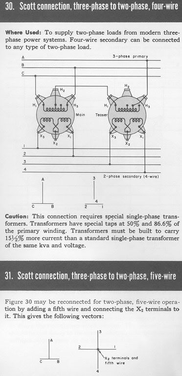
I think you are confusing a phasor diagram with a circuit diagram. Get that straight, then go back and read post 253 so you can understand what I am saying.
Then I would suggest you go read winnie's post #260 and answer his question
winnie said:
For example, if you operate on the principal that the phasors used to describe the two sides of a 120/240V single phase system should both be 120V 0 degrees, what phasors are used to describe the _three_ outputs of a 240/120 high leg single phase system?
I have already said you could show these with three phasors in a "T" orientation with the phasors Van, & Vbn, & Vcn. I did not suggest using Van, Vnb, & Vcn. In the general case, when neutral loads are present, I don't think I would use Vab, Vbc, Vca.
I you try to represent the shape of a circuit diagram by using phasors, you are limiting yourself on which phasors you can use. Again, a phasor diagram and circuit diagram are two different things.
coulter said:
This significance of this statement completely eludes me.
Simply stated, you can meter a 3 phase 3-wire with two stators but should use 3 stators for a 3 phase 4-wire. What you may decide to do for a 3-wire may be different than what you decide to do for a 4-wire.
coulter said:
...And, I don't ever remember doing a fault current analysis...Fault current analysis doesn't have much to do with the neutral...
Carl, when I first started playing when these circuits, I did not even know there was such a thing as fault current analysis. I was a child experimenting with circuits on my bedroom floor.
coulter said:
Fault current analysis doesn't have much to do with the neutral.
Did you just say that a neutral does not play a significant role during a fault?
[edit: typo]