single vs. 3 phase

Status
Not open for further replies.
jim dungar said:
Foward, opposite the engine thrust, is not a direction?

Then let me correct myself.

There are an infinite number of "real" or "actual" directions that the plane is traveling.

It really has nothing to do with the engine thrust. For example, in reference to the earth, some jet planes, when they land, can reverse the engine thrust through deflector plates. The plane is traveling one way, but the engine thrust is used for braking. The plane is traveling opposite the direction of the engine thrust.
 
jim dungar said:
I don't know which metering cts you are talking about with your "X" references. A standard utility KWH meter...
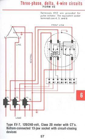
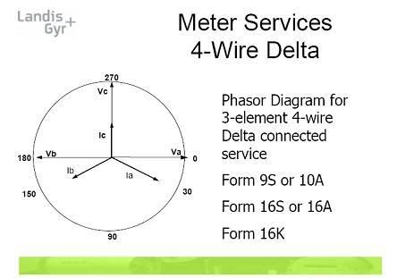
Please refer to the standard diagram from the GE meter installation guide. Also see the slide from a Landis & Gyr metering class that shows a 4-wire delta phasor diagram.
GE4Wdelta-9S.jpg
LG4Wdeltaphasordiagram.jpg
 
poor old Blondel

poor old Blondel

jim dungar said:
...meter for use on 120/240V 3-wire circuits has a single potential coil...A two-element wattmeter for 4-wire WYE loads...
Sure these meter setups are available, but they violate Blondel's Theorem and sacrifice accuracy.
 
mivey said:
Please refer to the standard diagram from the GE meter installation guide. Also see the slide from a Landis & Gyr metering class that shows a 4-wire delta phasor diagram.
GE4Wdelta-9S.jpg
LG4Wdeltaphasordiagram.jpg

As I mentioned above, there are reasons to pick different directions, in this case the meter manufacturer has chosen directions to make manufacturing the meter easier. Did you notice the voltages are in a Tee arrangement but the CTs are actually connected in a WYE? And that effectively the currents areflowing in the same direction as the voltages?
 
mivey said:
Sure these meter setups are available, but they violate Blondel's Theorem and sacrifice accuracy.

Such meter setups (A single L-L voltage coil) are not only available, but they are pretty much standard for 120/240V residential services.

-Jon
 
jim dungar said:
Did you notice the voltages are in a Tee arrangement but the CTs are actually connected in a WYE? And that effectively the currents areflowing in the same direction as the voltages?
That's why I picked this one, so I could show the "T" shaped voltage phasor diagram :grin:
winnie said:
Such meter setups (A single L-L voltage coil) are not only available, but they are pretty much standard for 120/240V residential services...
Absolutely true. They save money and the accuracy problem is not as big of a deal for those loads. The accuracy was more of an issue with unbalanced voltages.

The advantage to following Blondel's Theorem for the 4-wire delta was that a voltage imbalance does not impact the accuracy, and you had greater meter capacity in the lighting leg. I suspect the money saved by reducing the number of elements is getting to be less of a concern with today's electronic meters.
 
winnie said:
Such meter setups (A single L-L voltage coil) are not only available, but they are pretty much standard for 120/240V residential services.

-Jon

Actually I do not know of a residential meter that is not built this way.
 
jim dungar said:
Be careful.

There are T connected transfromers and Scott "Tee" connected units.

As I understand 'T connected transformers' of either type, you always have _2_ phase magnetic flux in two magnetic cores. The 'T' connection is a way of connecting three phases to two coils on the two cores.

If the other side of the transformer is simply two symmetric coils, then you have a 'Scott Tee' transformer converting between three and two phase. If the other side is another three phase 'T' connection then you have a three phase to three phase transformer.

Use a T connection for the secondary, and put a tap in the appropriate place, and you effectively have a 'wye' output.

IMHO, a T connected transformer of either type is a perfect example of a situation in which the most 'sensible' description of the output phase angle is not related to the polarity dots of the coils. In a T connected secondary, two of the outputs are the terminals of a _single_ coil, and must therefore be inverses of each other. Yet in my opinion the most sensible description of the output is as a three phase output, with phases 120 degrees apart.

-Jon
 
winnie said:
two of the outputs are the terminals of a _single_ coil, and must therefore be inverses of each other.

Jon, how can the outputs of a single coil be opposite each other? what point are you using for your reference?

Follow the polarity dots of a T output and compare them to the polarity dots of the T input are they different? Part of my discussion has always been to consider the physical construction of the transformer.

And just to be really really picky (I need to maintain my reputation), there is no T in the name of a Scott connection.
 
Last edited:
The Scott "T" Connection:

The Scott "T" Connection:

jim dungar said:
Jon, how can the outputs of a single coil be opposite each other? what point are you using for your reference?

Follow the polarity dots of a T output and compare them to the polarity dots of the T input are they different? Part of my discussion has always been to consider the physical construction of the transformer.

And just to be really really picky (I need to maintain my reputation), there is no T in the name of a Scott connection.

Jim, the point where the teaser coil crosses the main coil is the main coil is the reference node.

We could flip the polarity on the secondaries and still have 90 degrees. Your approach is logical and correct, but not mandatory. There are 64 ways the phasor diagram could be drawn, but I wouldn't.

Jim, I am perhaps pickier than thou, and my book describes a "T-connection (Scott connection)" My book is older than you as well.

The attached diagram clearly shows the reference point which may or may not be grounded.
 
Last edited:
From what I can find in my books, a Scott connection is used to go from 3-phase to 1 or 2 phase and vice versa. The 3-phase side had a neutral point available. It does have the 3-phase windings connected in a "T".

The Tee-Tee connection was primary for a 3-phase transformation but could also simultaneously supply 3, 2, and 1 phase loads. The primary and secondary had neutral points available. It, of course, has two "T" connections.

I found other odd stuff I've never heard of like double scott, double stars, double deltas, LeBlanc, Taylor, and Fortescue connections.
 
jim dungar said:
Jon, how can the outputs of a single coil be opposite each other? what point are you using for your reference?
If he is calling them opposites, then the point would be midway between the two outputs. The two outputs can't be the same unless they are at the same node.
jim dungar said:
Follow the polarity dots of a T output and compare them to the polarity dots of the T input are they different?
For a "T-T", I would think they would be the same. For the Scott, I'm not sure how that applies.
 
hardworkingstiff said:
And someone was wondering if this thread could hit 200 posts, lol. :)

Ya, that was me. I'm usually off by a factor of two...
So I guess that means 400 posts:confused: :roll:
 
engy said:
Ya, that was me. I'm usually off by a factor of two...
So I guess that means 400 posts:confused: :roll:
Hopefully we won't follow some derivative of Moore's Law
 
engy said:
Ya, that was me.
See 190.

Also Rick got #100 & #200 but Jim got #300. If Rick could have gotten all three we could have petitioned to have him kicked off (see #192):grin:

Oh, and while you are here, don't forget to sign the "shoot the cow" petition.
 
Status
Not open for further replies.
Top