single vs. 3 phase

Status
Not open for further replies.
weressl said:
...and of course would be wrong:)

There IS no such a thing as -120V in AC terminology.


Actually, half the time one conductor is considered positive and the other half of the time it is negative. At a single point in time, one conductor would be positive while the other is negative, precisely the same as DC voltage. 120 pulses per second. You actually have DC voltage for 120th of a second, it increases from 0v to max., then decreases back to 0v. Then you have another DC pulse occur for the next 120th of a second, but in the opposite direction. So surely, you can select a point in time and say that one conductor is positive while the other is negative. Is this incorrect? If so please explain as I would like to know. Don
 
crossman said:
This:

---------------------------------->
120v @ 0

equals this:

<----------------------------------
-120v @ 180

Is that correct?


Actually those two vectors are the same, (in phase with each other). To be 180? out of phase you would need to remove the negative sign on the bottom vector. Don
 
By convention, a vector represented in polar coordinates cannot have negative magnitude. There is no mathematical problem with negative magnitude; just as there is no mathematical problem with angles >360 degrees; but the entire plane may be represented by positive magnitude and 360 degrees, so convention places limits on the values used.

Negative magnitudes on vectors are as wrong as 'improper fractions'. (You know, 5/2 instead of 2 and 1/2)

-Jon
 
Algebra, y'all:

Algebra, y'all:

Don Randall said:
Actually those two vectors are the same, (in phase with each other). To be 180? out of phase you would need to remove the negative sign on the bottom vector. Don

Yes, they are equivalent. That is the reason the difference comes out to be 240 volts.
 
By the way:

By the way:

BTW, if we assume V1n = 120V @ 0, then V2n = 120V @ 180.

This is true regardless of the way the phasor diagrams are drawn. Just be sure the phase angles agree with the direction of the arrows.

Again, magnitudes are always positive. Signs of the real and imaginary components are determined by the signs of the sin and cos functions.

I am in disagreement with the learned Winnie on this one.
 
gar said:
080429-1659 EST

A few posts back the question was asked about connecting two separate secondaries in series. Simply add their vectors. If their magnitudes are the same, then opposing the sum is zero, and not opposing the output is 2 times one of the outputs. Use a voltmeter.

.

Rattus, if you will go to your breaker panel and use a voltmeter to measure the L1-N and L2-N voltages, do you add them together or subtract them from each other to determine the L1-L2 voltage? Keep it simple. Don

Actually, the question Gar was replying to was "secondaries in series and in phase) Don
 
Last edited:
engy said:
So L1-N and L2-N are not out of phase?

Then how do you explain L1-N = 120V while L2-N = -120V?
Seems to me the industry commonly uses neutral/ground as a reference point:-?

Actually my statement was that L1 and L2, (two conductors, not two circuits), are never out of phase with each other. Don
 
Don Randall said:
Rattus, if you will go to your breaker panel and use a voltmeter to measure the L1-N and L2-N voltages, do you add them together or subtract them from each other to determine the L1-L2 voltage? Keep it simple. Don

I would first measure V12 to verify that the feeders were wired correctly. Then I would measure V!n and V2n and check to see that V12 = V1n + V2n. This is all one needs to do in checking a panel, and since there is no phase angle info, it is all one can do.

However, a journeyman should understand that V1n and V2n are inverses and are therefore 180 degrees out even if he doesn't understand the math.

The key is using the CT as the reference. This notion does not conflict with the notion of series aiding coils. The phasors in both cases are equivalent, and V1n and V2n do not change.

Just imagine a two channel scope set up to view V1n and V2n. Sync on one channel or the other and observe the sinusoidal voltages. Crossman can probably simulate this for us or even perform the experiment.
 
Don Randall said:
My argument is not that N-L1 and N-L2 cannot be considered as circuits that are 180? out of phase with each other by people who want to take that view.

Don't say that! This thread might stop! :smile: ;) :cool:
 
Well, I didn't have time to read all the responses but this is my take on it.

Single phase = A to B

3 phase = A to B, B to C, A to C
 
Don Randall said:
I thought that a vector's polarity was indicated by its direction, not by + and - signs. Maybe my memory is failing me worse than I thought. Don

Yes, a vector/phasor should be represented by a magnitude and phase angle, however we sometimes negate/subtract a phasor in which case we prefix the vector/phasor with a negative sign. But the magnitude is always positive. The negation applies to the real and imaginary components of the phasor.
 
rattus said:
Just imagine a two channel scope set up to view V1n and V2n. Sync on one channel or the other and observe the sinusoidal voltages. Crossman can probably simulate this for us or even perform the experiment.

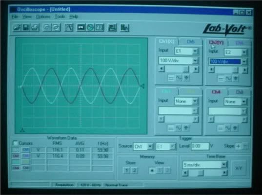
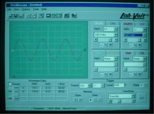
Here ya go Rattus! I actually performed the experiment, even though we all know what the results are beforehand.

Photo 1: This is the o-scope using the neutral as the reference. Channel 1 measures L1 to N and channel 2 measures L2 to N. The scope shows a 180 degree phase difference.

phase180.jpg


Photo 2: This is the o-scope with channel 1 measuring L1 to N and channel 2 measuring N to L2. Both sine waves coincide with each other.

phasein.jpg


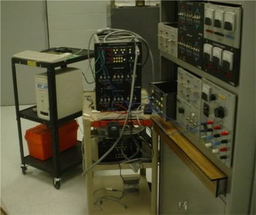
And a photo of the lab equipment:

phaselab.jpg


I think most electricians would consider that the neutral and earth would be the reference, but may not consider that this makes the two voltages 180 degrees out of phase which "seems" contrary to single phase.

Either way of measuring is correct. In the first photo, the L1 to N voltage and the L2 to N voltage ARE indeed 180 out of phase. You cannot say that using the neutral as the reference is a "trick" to make the voltages out of phase. There is more than one way to look at any problem in physics, depending on the reference frame one chooses.
 
winnie said:
By convention, a vector represented in polar coordinates cannot have negative magnitude. There is no mathematical problem with negative magnitude; just as there is no mathematical problem with angles >360 degrees; but the entire plane may be represented by positive magnitude and 360 degrees, so convention places limits on the values used.

Negative magnitudes on vectors are as wrong as 'improper fractions'. (You know, 5/2 instead of 2 and 1/2)

-Jon
This is not correct. In the mathematical solution to a problem, it is entirely acceptable to have negative magnitudes and larger than 360 degrees. The final answer is generally simplified into positive magnitudes and small angles. As Rattus notes below, albeit with an error, this is a simple example of a negative magnitude, and I have already cited a reference for it.
rattus said:
Yes, a vector/phasor should be represented by a magnitude and phase angle, however we sometimes negate/subtract a phasor in which case we prefix the vector/phasor with a negative sign. But the magnitude is always positive. The negation applies to the real and imaginary components of the phasor.
When you preface a vector with a negative sign (as used when inverting vectors--see my previous citation in another thread somewhere) you have in fact given it a negative magnitude to account for the inversion of the angle. It does not impact the rectangular coordinates because you have not changed them. Inverting a vector means that you have added 180 degrees to the angle, and given it a negative magnitude. The resulting vector and original vector remain mathematically equivalent. This permits the subtraction of vectors without violating the principle of commutation. As I have shown in the past, your vector diagrams are not commutative because you do not apply the very principle you stated.
 
Rick Christopherson said:
This is not correct. In the mathematical solution to a problem, it is entirely acceptable to have negative magnitudes and larger than 360 degrees.

Could you please clarify; you say that my comments were incorrect, but then you seem to repeat them. I said that negative magnitudes and angles outside of a 360 degree range are mathematically acceptable, and wrong only by convention.

-Jon
 
Don Randall said:
Can you show the same two setups again, but using the add function? Don

Sorry, already put the equipment away and am to weary to get it out again.

One thing to be understood concerning "adding".... when we use the neutral of the single-phase, 3-wire system as a reference, and then we take a voltage measurement from two points which does not include the neutral, we are actually measuring the potential DIFFERENCE of the two points and we must subtract, not add.
 
crossman said:
This:

---------------------------------->
120v @ 0

equals this:

<----------------------------------
-120v @ 180

Is that correct?
I would have thought:
---------------------------------->
120v @ 0

equals this:

---------------------------------->
-120v @ 180

[edit: spelling]
 
Last edited:
Here is 600

[edit:
Rick Christopherson said:
...In the mathematical solution to a problem, it is entirely acceptable to have negative magnitudes and larger than 360 degrees...
I don't get the whole emphasis on the negative that rattus is making. You could say the "2" in "-2" is a positive number. What is the difference in having -|#|<0 and |#|<180. Even on a vector diagram you could note the vector 120<120 as -120<300. Did I miss a point?]
 
Last edited:
Status
Not open for further replies.
Top