single vs. 3 phase

Status
Not open for further replies.
crossman said:
Sorry, already put the equipment away and am to weary to get it out again.

One thing to be understood concerning "adding".... when we use the neutral of the single-phase, 3-wire system as a reference, and then we take a voltage measurement from two points which does not include the neutral, we are actually measuring the potential DIFFERENCE of the two points and we must subtract, not add.

When you say potential DIFFERENCE, you are referring to VOLTAGE,(difference of potential), or EMF aren't you. Or are you implying that it is used as a math function in this context? Don
 

crossman

Senior Member
Location
Southeast Texas
Don, one point that may be missing is that vectors represent forces by using length. When we combine them, we are not so much "adding" them as we are measuring the distance from the beginning of 1 to the end of the other.

For example, in the Cartesian plane, to find distance between two points, we take (X2 - X1) and (Y2 - Y1) and then put the results in the Pythagorean theorem. If there is no Y component, then the whole thing boils down to subtracting one X term from the other.
 
Don Randall said:
Can you show the same two setups again, but using the add function? Don
Crossman, Maybe when you get rested up, you could do this and shed some light on those of us who may not understand. You could show the same results as before and include photos of the waveforms when you use the add function. Surely that scope can add two sine waves. Then you can explain to us why the results on the scope are wrong. Don
 

crossman

Senior Member
Location
Southeast Texas
Don Randall said:
Surely that scope can add two sine waves. Then you can explain to us why the results on the scope are wrong. Don

I don't quite understand what you mean. The results are wrong?

The results aren't wrong. Both results are correct. The use of the neutral as a single reference versus not using a single reference when measuring the voltages changes the perameters used for solving the math. Both approaches are equivalent. The physics is exactly what it is regardless of the choosen frame of reference.

BTW, this multi-channel scope actually does not have an "add" function. I would have to do the add by connecting channel 3 into L1 and L2.
 

rattus

Senior Member
mivey said:
Here is 600

[edit:
I don't get the whole emphasis on the negative that rattus is making. You could say the "2" in "-2" is a positive number. What is the difference in having -|#|<0 and |#|<180. Even on a vector diagram you could note the vector 120<120 as -120<300. Did I miss a point?]

Yes, you could, but:

1. I think this is poor form and confusing for a phasor diagram. You should draw 120 @ 120. There is no reason to draw the diagram this way. Save the negation for the analysis.

2. In the split phase system, Vmag = Vrms which is positive by definition, that is, a positive square root.

3. Insertion of a negative sign before Vmag changes the signs of the sine and cosine terms--not Vmag.

Example:

Vrms @ 45 = Vrms(0.707 + j(0.707))

-Vrms @ 45 = Vrms@ 225 = 120V(-0.707 -j(0.707))

Vrms always carries a positive value. Right Laszlo?
 
crossman said:
I don't quite understand what you mean. The results are wrong?

The results aren't wrong. Both results are correct. The use of the neutral as a single reference versus not using a single reference when measuring the voltages changes the perameters used for solving the math. Both approaches are equivalent. The physics is exactly what it is regardless of the choosen frame of reference.

BTW, this multi-channel scope actually does not have an "add" function. I would have to do the add by connecting channel 3 into L1 and L2.

Sorry, I meant the results of using the add function would be wrong. They would show the in phase sine waves adding to double whatever they are now, and the out of phase sine waves would cancel each other out and equal zero. On my old B&K scope I can just flip a switch down, four selections, Channel A, Channel B, Dual, and Add. If it's a bother, don't worry about it. Don
 

rattus

Senior Member
Don Randall said:
Crossman, Maybe when you get rested up, you could do this and shed some light on those of us who may not understand. You could show the same results as before and include photos of the waveforms when you use the add function. Surely that scope can add two sine waves. Then you can explain to us why the results on the scope are wrong. Don

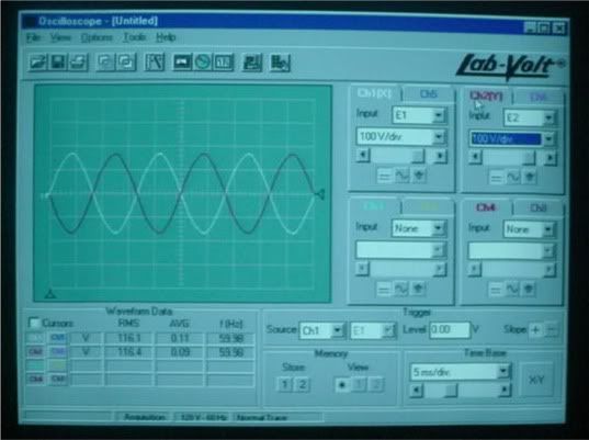
Don, there is no addition or subtraction. In the first photo, you are seeing the voltages V1n and V2n which are clearly equal and opposite and out of phase by 180. If you add them, the result will be zero. If you subtract them, the result will be 240V.

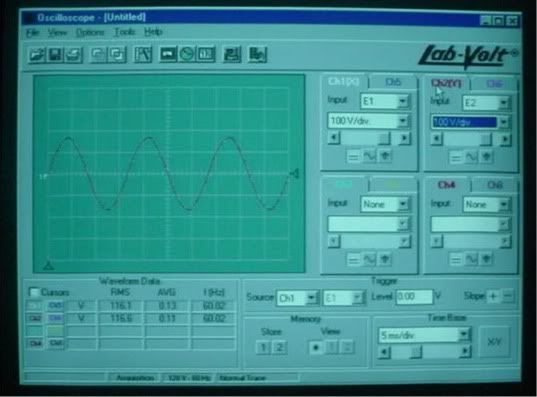
In the second photo, you are seeing V1n and V2n which are equal and appear as a single wave. Addition here will yield 240V.

Try to find a primer on phasors which some call vectors although strictly speaking, they are not. They are just drawn that way, like Jessica Rabbit.
 
rattus said:
Don, there is no addition or subtraction. In the first photo, you are seeing the voltages V1n and V2n which are clearly equal and opposite and out of phase by 180. If you add them, the result will be zero. If you subtract them, the result will be 240V.

In the second photo, you are seeing V1n and V2n which are equal and appear as a single wave. Addition here will yield 240V.

Try to find a primer on phasors which some call vectors although strictly speaking, they are not. They are just drawn that way, like Jessica Rabbit.
Rattus, I didn't really make myself clear. I meant the results of using the add function would be wrong as stated above. Those results of course would be correct for the waveforms shown on the scope, but would prove not to agree with your view. Don
 

crossman

Senior Member
Location
Southeast Texas
Don Randall said:
Those results of course would be correct for the waveforms shown on the scope, but would prove not to agree with your view. Don

What exactly is the "add" function? Just a mathematical addition of the two waves done by a microprocessor in the scope?
 
crossman said:
What exactly is the "add" function? Just a mathematical addition of the two waves done by a microprocessor in the scope?
I don't really know, but I would assume that it just switches both inputs to one amplifier and they would combine just as in any circuit. Different scopes may have different ways of handling it. Don
 
Don Randall said:
I don't really know, but I would assume that it just switches both inputs to one amplifier and they would combine just as in any circuit. Different scopes may have different ways of handling it. Don
I just looked at a diagram. Individual inputs go to input attenuators, then to amplifiers, then to the channel-dual-add switch. A block diagram so no real details. Don
 

mivey

Senior Member
rattus said:
...In the second photo, you are seeing V1n and V2n which are equal and appear as a single wave. Addition here will yield 240V...
Did you mean to say:
In the second photo, you are seeing V1n and Vn2 (or -V2n) which are equal and appear as a single wave. Addition here will yield 240V
 

rattus

Senior Member
Oops:

Oops:

mivey said:
Did you mean to say:
In the second photo, you are seeing V1n and Vn2 (or -V2n) which are equal and appear as a single wave. Addition here will yield 240V

How embarrassing. Thanks for your sharp eyes.
 

rattus

Senior Member
Any doubters out there?

Any doubters out there?

crossman said:
Here ya go Rattus! I actually performed the experiment, even though we all know what the results are beforehand.

Photo 1: This is the o-scope using the neutral as the reference. Channel 1 measures L1 to N and channel 2 measures L2 to N. The scope shows a 180 degree phase difference.

phase180.jpg


Photo 2: This is the o-scope with channel 1 measuring L1 to N and channel 2 measuring N to L2. Both sine waves coincide with each other.

phasein.jpg


I think most electricians would consider that the neutral and earth would be the reference, but may not consider that this makes the two voltages 180 degrees out of phase which "seems" contrary to single phase.

Either way of measuring is correct. In the first photo, the L1 to N voltage and the L2 to N voltage ARE indeed 180 out of phase. You cannot say that using the neutral as the reference is a "trick" to make the voltages out of phase. There is more than one way to look at any problem in physics, depending on the reference frame one chooses.

Good work Crossman! Now, after viewing these oscillographs, does everyone now agree that the voltages on L1 and L2 in a split-phase service are inverses and exhibit a phase difference of 180 degrees?

WYSIWYG!
 
rattus said:
Good work Crossman! Now, after viewing these oscillographs, does everyone now agree that the voltages on L1 and L2 in a split-phase service are inverses and exhibit a phase difference of 180 degrees?

WYSIWYG!
Not unless you include neutral in your statement, L1 to N and L2 to N. Which of course is actually reversing the scope leads for one of the readings. L1 and L2 are always in phase with each other. Don
 

rattus

Senior Member
Don Randall said:
Not unless you include neutral in your statement, L1 to N and L2 to N. Which of course is actually reversing the scope leads for one of the readings. L1 and L2 are always in phase with each other. Don


Don,

That is my point. When we define the voltages on nodes L1 and L2, we are defining the voltages on L1/L2 relative to the CT/N/G, and to do this we must place the red lead on L1/L2 and the black lead on the CT/N/G because that is the only node left to use as a reference.

We are not defining the neutral voltage relative to L1/L2. It is the other way around.

It is consistent to define V1 and V2 this way because this is exactly what is done with Va, Vb, and Vc in a wye. We automatically know they are defined relative to the neutral. No one tries to change the reference with the wye!

Now, in analyzing circuits, one can do what one desires. I am only arguing the meaning of V1 and V2 on L1 and L2.
 

coulter

Senior Member
rattus said:
... It is consistent to define V1 and V2 this way because this is exactly what is done with Va, Vb, and Vc in a wye. ...
Interesting comment - but not valid. This single phase connection has nothing to do with a 3ph Wye.

Instead compare the single phase (drawn with back to back arrows) to a 3ph delta. At least you can get to 1ph 120/240 to from 3phD. Now, all those back to back arrows and currents reversing direcion as they go through the magic "N" point look silly. Remember "yum", "yuk", and "puk".

rattus said:
... I am only arguing the meaning of V1 and V2 on L1 and L2.
As we all know, "the voltage" of an isolated point doesn't exist, voltage measurements always have to have two leads. But the second lead does not have to be stuck to the magic "N" point. I would tend to match up the direction of all the voltage drops around a loop - including the two across the two series sources that make 1ph. There is no reason to reverse one of the source polarities just because someone labled a circuit point "N".

rattus said:
... Now, in analyzing circuits, one can do what one desires. ...
As I have said, this insistance on teaching the meaning of V1-L1, V2-L2 for single phase is not crippling - single phase analysis is trivial. However the extension of the silliness to other systems such as 3phD is limiting Why would one analyze a 3phD using the 'puk" diagram.

carl
 

rattus

Senior Member
coulter said:
Interesting comment - but not valid. This single phase connection has nothing to do with a 3ph Wye.
Yes, they do. Both have neutrals, so why not measure the voltages in the same manner?
As we all know, "the voltage" of an isolated point doesn't exist, voltage measurements always have to have two leads. But the second lead does not have to be stuck to the magic "N" point.
Yes it does if one is measuring voltage and phase on one of the hots, that is V1 or V2. There is no other place to put the black lead.
As I have said, this insistence on teaching the meaning of V1-L1, V2-L2 for single phase is not crippling - single phase analysis is trivial. However the extension of the silliness to other systems such as 3phD is limiting Why would one analyze a 3phD using the 'puk" diagram.

carl

I don't see anything crippling about it. It is just steady state analysis, and as I said you can analyze any way you wish.

Just think of a black box with 3 test jacks--red, black, and red. Now you are asked to describe the AC voltages on the red jacks relative to the black one. Where would you put your test leads?
 

mivey

Senior Member
rattus said:
...Now you are asked to describe the AC voltages on the red jacks relative to the black one. Where would you put your test leads?
He would probably put them in the jugular of the one who asked him to do that.:D
 
Status
Not open for further replies.
Top