100A MCB in adjacent panel.
Feeder goes to panel board. Here it splits. One feeder to bottom panel, 120V SP breaker feeds timer.
Rest is direct feed to line side of contactor. Load side of contactor feeds upper panel, with all individual lighting breakers.
Out of timer is the two switch legs, standard, and a neutral, to line side of relay. Load side of relay is black and red. 12” away, someone extended the red wire with A piece of black, and the black with a piece of red. Why I don’t know.
The output of this relay is shown as 30VDC. Red and black land on A1 and A2 of new contactor.
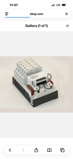
New contactor is an ABB AF-52-30-11-13. My supplier found it for me, based on needing a 3 phase contactor for 208Y, at minimum 75 Amps, as that is what was there before. Box says 100-250VAC. Worthless papers shipped in the box show short circuit rating for 480 and 600 volts.
I cannot seem to find any info on what the required input voltage on the control circuit is. When I called them yesterday at 1:00 in the afternoon, they were already closed.

I did find one website where it said input voltage on the control circuit is 20-60VDC, and 24-60VAC. I usually just run the control wires from the Intermatic direct to the A1 and A2, but I can’t seem to confirm this is what this contactor can handle.