Ground fault- Why doesn't anyone get shocked?

Status
Not open for further replies.
Using 34.5 kV, 3ph OH primary wye MGN, large wire (556 ph, 336 neu), I_fault at sub = 9.47 kA LLL, 11.5 kA LN.

N-E voltage for L-N primary fault at service transformer:

1 SPAN (11.1 kA): 216 V
1/4 MILE (9.7 kA): 916 V
1/2 MILE (8.4 kA): 1.52 kV
1 MILE (6.7 kA): 2.2 kV
2 MILES (4.9 kA): 2.4 kV
3 MILES (4.0 kA): 2.2 kV
4 MILES (3.3 kA): 1.8 kV

HUGE thanks. :happyyes:

I somewhat anticipated these numbers.


So, how are those 2.4kv rendered safe? Does this mean I should stick to 12.47kv distribution? What do the numbers look like for that?


Does your model assume metal water mains or just take the 336 neut and its ground rods?
 
So, how are those 2.4kv rendered safe?
Body resistance and breaker clearing time.

Does this mean I should stick to 12.47kv distribution?
Nope

What do the numbers look like for that?
Similar

Does your model assume metal water mains or just take the 336 neut and its ground rods?
I modeled some low endpoint impedances to account for multiple earth attachments but not a particular parallel line. Most water lines are going to plastic nowadays.

I can model in a pipe but not much would change. N-E voltage might drop slightly but elsewhere on the system you would get similar results. This is not a specific model or a model to fit all cases, just an example to show the drill may have thousands of volts on it during the fault.
 
Forget the neutral. That might be a load current path but in a ground fault its not very important at all for the example which is utility systems.

A little known fact is that the conceptual idea we've been taught that electricity follows the path of least resistance is utterly false. It actually follows all paths proportional to their conductance which is the inverse of resistance. This becomes important when we move from a 1D system to grounding which is clearly 2D. As the ground electrode on say a pole gets further from the substation ground it would seem that resistance increases. On any given path this is true and it's basically linear but the number of paths between the two depends on the area between them so it's increasing with the square of the distance. So when we divide by the number of paths the surprising fact is that Earth resistance is proportional to the inverse of distance. Even though Earth isn't a great conductor usually about a mile away the resistance equals the neutral (which is increasing) and quickly surpasses it within a few miles to where effectively it's almost a dead short to the substation. Thus almost the entire voltage drop is over the hot and the neutral voltage drop is almost zero. You can verify this in the IEEE green book or just look at the formulas in any 3 point ground testing manual where you divide by the distance to get resistance. Within a typical structure there are tons of research papers that show that conduit resistance is far less than the neutral so once again, the neutral sees little to no voltage during a fault. It's only close to the transformer or within a substation, or close to a faulted transmission tower that ground potential rise or GPR actually becomes a serious safety hazard. Even then the danger isn't the fact that say the tower or the Earth is energized. It's the gradient or difference through the ground so foot to foot is the hazard. That's why they teach linemen to keep their feet together and shuffle or bunny hop if they are caught near a downed line and need to escape. So going back to the OP, there is little or no neutral voltage. To the post about SKM output that's at the transformer, not close to the fault.

The original Edison DC distribution systems used a single hot and peg grounding as the return. There were lots of safety reports near these systems, all GPR issues.

Today we use extensive grounding under substation yards and multigrounded and bonded systems everywhere else. Because of GPR line crews are moving to using equipotential grounding as well as ground grid blankets for ground men to reduce or eliminate GPR on work sites.

Sent from my SM-T350 using Tapatalk
 
Body resistance and breaker clearing time.

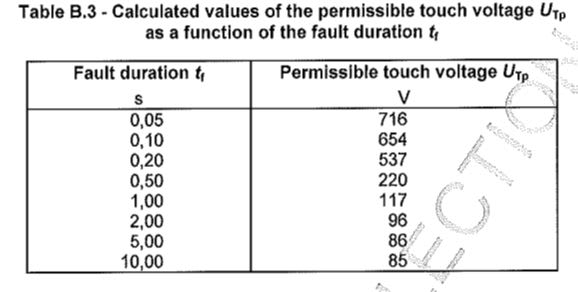
Which could take 25 cycles if not more out on the trunk (inverse time over current + oil breaker + possible breaker failure relaying initiation)- violating IEC/TR 60479-5 and IEC/TR 61200-413, specifically:


677px-DB422220_EN.svg.png


Gonna need some proof/inspiration ;)


Why similar though? I'd imagine less voltage would mean less voltage to remote earth in general.

I modeled some low endpoint impedances to account for multiple earth attachments but not a particular parallel line. Most water lines are going to plastic nowadays.

Which would only increase the voltage- and the scenario I fear/ think about.

I can model in a pipe but not much would change. N-E voltage might drop slightly but elsewhere on the system you would get similar results. This is not a specific model or a model to fit all cases, just an example to show the drill may have thousands of volts on it during the fault.


How likely is it to have thousands of volts though? I can't see those thousand of volts not being harmful beyond a few cycles, if that.

In the old days with ungrounded systems, I remember the pole pig can was grounded via one ground rod, and then the LV with another dedicated ground rod X feet from the pole.
 
Last edited:
From IEC/TR 61200-413, figure 14 which I am basing my assumptions:
 

Attachments

  • Figure 14.jpg
    Figure 14.jpg
    109.5 KB · Views: 0
Last edited:
Forget the neutral. That might be a load current path but in a ground fault its not very important at all for the example which is utility systems.
Incorrect. The OP was about a phase conductor getting knocked down by a tree and making contact with the neutral.

A little known fact is that the conceptual idea we've been taught that electricity follows the path of least resistance is utterly false. It actually follows all paths
One of the only truly accurate things in your post. And it is a well known fact on this forum from what I've seen, but maybe not by all.

Even though Earth isn't a great conductor usually about a mile away the resistance equals the neutral (which is increasing) and quickly surpasses it within a few miles to where effectively it's almost a dead short to the substation. Thus almost the entire voltage drop is over the hot and the neutral voltage drop is almost zero. You can verify this in the IEEE green book or just look at the formulas in any 3 point ground testing manual where you divide by the distance to get resistance. Within a typical structure there are tons of research papers that show that conduit resistance is far less than the neutral so once again, the neutral sees little to no voltage during a fault. It's only close to the transformer or within a substation, or close to a faulted transmission tower that ground potential rise or GPR actually becomes a serious safety hazard. Even then the danger isn't the fact that say the tower or the Earth is energized. It's the gradient or difference through the ground so foot to foot is the hazard. That's why they teach linemen to keep their feet together and shuffle or bunny hop if they are caught near a downed line and need to escape. So going back to the OP, there is little or no neutral voltage. To the post about SKM output that's at the transformer, not close to the fault.
Not much of that is accurate at all. About the only thing close to true is the better grounds can help reduce the N-E voltage to some degree.
 
Gonna need some proof/inspiration ;)
You will have available fault currents at either voltage that will provide proper stiffness to adequately serve the loads.

Why similar though? I'd imagine less voltage would mean less voltage to remote earth in general.
To some degree but the fault current will be similar to the load centers. With 35 kV you can travel further and have fewer load centers and with 12 kV you will have more stations near more load centers.

How likely is it to have thousands of volts though?
As a percentage of miles of line, relatively small but still a possibility. I thought we were discussing kind of the bad scenario instead of the good scenario correct?

In the old days with ungrounded systems, I remember the pole pig can was grounded via one ground rod, and then the LV with another dedicated ground rod X feet from the pole.
Better to use two ground rods at the pole unless you have great soil. For less that great soil, we also ground every primary pole nowadays and not just equipment poles and every 1/4 mile.
 
You will have available fault currents at either voltage that will provide proper stiffness to adequately serve the loads.

Ok- but why would voltage to remote earth be similar?


To some degree but the fault current will be similar to the load centers. With 35 kV you can travel further and have fewer load centers and with 12 kV you will have more stations near more load centers.

What MV loading would you do for per station for 12kv vs 35kv? MVS effects stiffness and short circuit.


As a percentage of miles of line, relatively small but still a possibility. I thought we were discussing kind of the bad scenario instead of the good scenario correct?

Bad scenario- or rather a code minimum system with limited parallel paths.


I would think all conditions are considered in the NESC code's grounding requirements such that under worst case clearing there is no possibility of a person referenced to remote earth being burned or any significant risk of sustained ventricular fibrillation.

But 2,400 volts... I can't see that not doing harm for 35 cycles.

Either the assumptions are wrong, or the NESC is wrong. And please don't take this as put down- because I have way less faith in the code then I have in you :):)


Better to use two ground rods at the pole unless you have great soil. For less that great soil, we also ground every primary pole nowadays and not just equipment poles and every 1/4 mile.


Or more ground rods per mile, I think that would be the best over all correct?
 
Incorrect. The OP was about a phase conductor getting knocked down by a tree and making contact with the neutral.

One of the only truly accurate things in your post. And it is a well known fact on this forum from what I've seen, but maybe not by all.

Not much of that is accurate at all. About the only thing close to true is the better grounds can help reduce the N-E voltage to some degree.
The formula for cable resistance is L x p where L is cable length and p is the resistance per unit length. This is exactly what we would intuitively expect. But this is for a cable in space or for short distances where impedance can be ignored.

Earth resistance if the distance between electrodes is large compared to depth is rho = 2×pi×A×R where R is the resistance in ohms, A is the distance between electrodes, and rho is soil resistivity in ohm-meters. This is basic text book stuff here. If we solve for R we get:

R = rho / (2 × pi x A)

We are dividing by the distance A here, not multiplying! In average soils rho varies from around 150-1,000 ohm-meters. So even at 1,000 ohm-meters at around 160 meters we are down to 1 ohm. At 1 km away it's only 0.16 ohms. By that point resistance is far lower than a cable of the same length, so the resistance of the neutral, not Earth, can be ignored. Even in very poor rocky soils rho could be much higher but it just determines at what point we go from a "local" to a "remote" Earth model. Based on personal experience in open pit mining generally this happens at about a mile away based on Eastern US conditions. The distance will increase in say New Mexico but not the principle behind it.

So now getting to your invalid N-E argument a standard utility multigrounded system has a neutral/static line grounded at every pole. This is done primarily for the purpose of controlling transients among other concerns. Not grounding is a huge Code (NESC this time) and safety violation. So I would completely agree N-E does not apply because it is equal to zero where you are incorrectly assuming it is some large value which can be ignored. Because of this fact we cannot ignore Earth resistance since the Earth and neutral lines are in parallel with each other as well as shorted together at multiple points. Based on Earth resistance, we can safely ignore resistance in the neutral and use Earth resistance which is nearly zero as well. Thus the drop is all on the phase conductor.

You simply cannot take the grossly oversimplified view that Earth resistance has no bearing on utility distribution systems with the simplified assumption that Earth resistance is so high that it can be ignored. It is not so simple with utility systems. Heck with your model we wouldn't need static lines, pole grounds, or really even substation grounding at all! Even switching transients would not exist. You need to use the full transmission line model, not just a 2 wire loop in space with no consideration for capacitive coupling or Earth resistance, whenever line length exceeds a few hundred feet. That is what is missing here and why energized structures as well as GPR rise behave differently from what you would expect. In fact GPR would not exist in a L-N fault in your scenario. It clearly does as anyone working faults can tell you.


Sent from my SM-T350 using Tapatalk
 
Ok- but why would voltage to remote earth be similar?
Not enough difference to choose 12 kV over 35 kV. That choice is driven by load size, density, and distance.

What MV loading would you do for per station for 12kv vs 35kv? MVS effects stiffness and short circuit.
Station size is based on load size and density. I like individual feeders at below 600 amps and generally try to keep them loaded in the 300-400 amp range to allow for contingency load switching. The line design and mechanical loading is easier at those levels although I have had to use some 1200 amp circuits before.

Bad scenario- or rather a code minimum system with limited parallel paths.


I would think all conditions are considered in the NESC code's grounding requirements such that under worst case clearing there is no possibility of a person referenced to remote earth being burned or any significant risk of sustained ventricular fibrillation.

But 2,400 volts... I can't see that not doing harm for 35 cycles.

Either the assumptions are wrong, or the NESC is wrong. And please don't take this as put down- because I have way less faith in the code then I have in you :):)
Nothing in this world is perfectly safe. The safer you get the more it costs and people will call for cheaper power. We live in a world of probabilities, cost, safety, and lawyers arguing every side of every argument.

Or more ground rods per mile, I think that would be the best over all correct?
Every system is different. More ground rods has a diminishing return. Four per mile has been determined to be a compromise. IIRC, there is little lightning benefit beyond about 6-8 per mile but I would have to look it up.
 
This is basic text book stuff here.
You need to move beyond basic text book stuff. It is more complex than you realize.

So even at 1,000 ohm-meters at around 160 meters we are down to 1 ohm. At 1 km away it's only 0.16 ohms. By that point resistance is far lower than a cable of the same length,
That is not how it works. You would do well to study Carson's equations and the associated calculations for overhead transmission line impedance and fault modeling. I have quite a few posts about that here and even went through the formulas and calcs (I think I completed the series anyway...don't remember).

so the resistance of the neutral, not Earth, can be ignored.
You can't ignore either one.

Based on personal experience in open pit mining generally this happens at about a mile away based on Eastern US conditions. The distance will increase in say New Mexico but not the principle behind it.
I would be interested in hearing about these experiences as I have not worked in pit mining.

However, these experiences seem to have led to some peculiar conclusions. There may be something different you are talking about but in the context of the OP they appear at first glance to be way off. One would expect empirical data to generally align with accepted engineering theory and practice.

So now getting to your invalid N-E argument a standard utility multigrounded system has a neutral/static line grounded at every pole. This is done primarily for the purpose of controlling transients among other concerns.
A straw-man argument. That is not practice by standards but practice by experience in certain areas. The standard is still 4/mile plus at equipment poles. In today's world of broken grounds and wire theft we see many utilities practice grounding every primary pole in places. This will vary, even internally to an individual utility. Soil conditions, lightning frequency, population density, economics, reliability index, etc. all play a role.

Not grounding is a huge Code (NESC this time) and safety violation.
Well its a good thing no one is suggesting that then isn't it?

So I would completely agree N-E does not apply because it is equal to zero where you are incorrectly assuming it is some large value which can be ignored.
Your premise is not supported by engineering standards or analysis.

Because of this fact we cannot ignore Earth resistance since the Earth and neutral lines are in parallel with each other as well as shorted together at multiple points. Based on Earth resistance, we can safely ignore resistance in the neutral and use Earth resistance which is nearly zero as well. Thus the drop is all on the phase conductor.
You are simply wrong. Near a ground fault, the current travels mostly in the earth but quickly climbs the pole grounds on the way to the station. The current tends to follow the line and if long enough, about 1/2 will travel in the earth and 1/2 on the neutral in the middle of the circuit. More will travel on the neutral at the endpoints

You simply cannot take the grossly oversimplified view that Earth resistance has no bearing on utility distribution systems with the simplified assumption that Earth resistance is so high that it can be ignored.
Another straw-man argument and not what I have said at all.

It is not so simple with utility systems. Heck with your model we wouldn't need static lines, pole grounds, or really even substation grounding at all!
The model I use is the same model used by transmission and distribution engineers all over the world. It is not something I came up with.

The model(s) you have been supposing I'm using comes from who knows where.

Even switching transients would not exist. You need to use the full transmission line model, not just a 2 wire loop in space with no consideration for capacitive coupling or Earth resistance, whenever line length exceeds a few hundred feet. That is what is missing here and why energized structures as well as GPR rise behave differently from what you would expect. In fact GPR would not exist in a L-N fault in your scenario. It clearly does as anyone working faults can tell you.
You are making assumptions about a model that has not been proposed by me so you are arguing against some strange model that you came up with, not one I use.
 
Not enough difference to choose 12 kV over 35 kV. That choice is driven by load size, density, and distance.

I'm still a bit skeptical- the voltage to remote earth has to be higher- though the odds of faster clearing do go up.


Station size is based on load size and density.


To a degree though- I've found that at 12.47kv you are generally limited to 40-80MVA loading tops, 100-120MVA at 23kv, and at 34.5kv I've seen 200MVA and over.


I like individual feeders at below 600 amps and generally try to keep them loaded in the 300-400 amp range to allow for contingency load switching.

Indeed :) 50 to 65% of 600amps is my target loading to allow for easy switching. Open the first source recloser or switch, close the nearest tie.


The line design and mechanical loading is easier at those levels although I have had to use some 1200 amp circuits before.

Dedicated transmission right-of-ways? Can tap lots of distribution with excellent reliability doing that way.


Nothing in this world is perfectly safe. The safer you get the more it costs and people will call for cheaper power. We live in a world of probabilities, cost, safety, and lawyers arguing every side of every argument.

Every system is different. More ground rods has a diminishing return. Four per mile has been determined to be a compromise. IIRC, there is little lightning benefit beyond about 6-8 per mile but I would have to look it up.


But how do we know this will always result in safe values of neutral to remote earth voltage?

Can I be candid if I may? I have a feeling that current NESC practices can and do place injurious voltages on people referenced to remote earth.


35+ cycles and 2,400 volts violates IEC 60479-1 and IEC 60479-5.
 
Status
Not open for further replies.
Top