Just to clarify.

Status
Not open for further replies.
Brainwashed!

Brainwashed!

Before, if I were given the 3 resistor circuit, I would not have thought about life being easier by changing the reference point to b. I would just run the loops and crunch it out. As a matter of fact, when I first ran the 3 resistor circuit, I just made my loops and solved my 3x3 matrix. No problem (not with HP power). It is not as obvious with a single resistor circuit because you are intuitively chopping steps out in your head and really just write down the answer, so it looked like it was just a fuss about a negative sign.

When I went back and started going through all that blueberry mess, I started stepping through the currents and voltages instead of writing loop equations. When I started doing that for the 3 resistor case, it becomes obvious that the corner "driving voltage" notion can make your life easier. Sounds good to me.

By the way, the whole discussion about -A not equal to A at 180 degrees was a major distraction. Another distraction was the 180 degree vs opposite phase vs polarity topic. Once you get past all that nonsense, you can see the value of the driving voltage for the simple circuit.

Jim, I finally get what you mean when you say "just because you can, doesn't mean you should"

For simple circuits, I'm calling myself brainwashed on this. I'm not sure about the complex circuit and if the driving voltage notion keeps life easy because I'm not sure if I would step through the circuit or make a loop analysis. I sure don't feel like doing it right now.

[edit: typo]
 
Last edited:
bcorbin said:
I'll add my two cents here regarding the reference issue. I don't think reference to the neutral "point" makes much sense. It takes two points to have a voltage difference, and any other voltage, in phasor notation or otherwise, would be referenced to that voltage in both magnitude and direction.

Its a matter of the notation that you are using.

As you note, every voltage difference requires two points for the measurement.

Consider a circuit that has 10 different nodes.

You can define/measure the voltage between any pair of nodes, for a total of 90 different voltage measurements. (There are 2 possible measurements for each pair, since you can pick one of two senses for each measurement.) In this case your measurements are associated with _pairs_ of nodes.

Or you could choose to select any one node as your reference. All voltage measurements are made relative to this node, and the reference is always on the same side for 'sense'. In this case there are only 9 different voltage measurements, each associated with a single node.

The two approaches are equivalent, and you can move from one representation to the other as needed for a given problem.

-Jon
 
mivey said:
Jim,

Now that I've conceded the corner point for a simple circuit, can the same be said for finding the internal voltages and currents for something complex, say like this:


Just at first thought, I wouldn't think the corner is any easier than the neutral. It's not obvious to me, but what do you say?

Actually I have not been advocating a corner reference as much as I have been arguing against this specific use of 120V @180?. My point has been to keep the driving voltage source in the same direction as its current.

My statement "just because you can doesn't mean you should" could be used to justify choosing the reference point n in your network.
 
rattus said:
True,

Van = Vnb = 115V @ 0.

You are using different references for the two sources. Use "n" for the common reference.
Mivey just said about the same thing, so even though I am quoting Rattus, I am asking this of both of you.

How did you know that this diagram was "using a different reference"? Where in any of the diagrams in this entire thread was there some sort of indication as to a reference point?

Exercise: Without making any assumptions of any kind, take a hypothetical voltmeter (i.e. one that displays polar coordinates) and place one probe on "n" and move the other probe from "a" to "b". Record the following voltages for both the single resistor diagram, and for the complex diagram: (I'll use your notation where Vbn = Voltage from n to b)
Vbn=
Van=
Vab=
====================================

Rather than waiting for results, I will jump ahead with the explanation:

When you draw a circuit diagram, there are no reference points. Those are just voltage sources stuck between labeled points. A specific or chosen reference point doesn't come into play until you start writing equations for the circuit. Two different people that have no prior knowledge of a circuit diagram should be able to solve the diagram and get the same answer, regardless what their chosen reference point is for their set of equations.

For the single resistor circuit you should have gotten:
Vbn = -115@180 = 115@0
Van = 115@0
vab = 0

For the complex circuit you should have gotten:
Vbn = -115@0 = 115@180
van = 115@0
vab = 230@0

Edit: I type too slow. 4 postings came in saying about the same thing while I was writing this. Sorry.
 
Last edited:
Rick Christopherson said:
Edit: I type too slow. 4 postings came in saying about the same thing while I was writing this. Sorry.


I was not quite saying the same thing. I was saying that there was an inconsistency in the first drawing that could lead one to pick either sense for the voltage Vbn, and thus a total voltage of 230 or 0, depending upon how you interpreted the drawing.

-Jon
 
Rick Christopherson said:
Mivey just said about the same thing, so even though I am quoting Rattus, I am asking this of both of you.

How did you know that this diagram was "using a different reference"? Where in any of the diagrams in this entire thread was there some sort of indication as to a reference point?

Exercise: Without making any assumptions of any kind, take a hypothetical voltmeter (i.e. one that displays polar coordinates) and place one probe on "n" and move the other probe from "a" to "b". Record the following voltages for both the single resistor diagram, and for the complex diagram: (I'll use your notation where Vbn = Voltage from n to b)
Vbn=
Van=
Vab=
====================================

Rather than waiting for results, I will jump ahead with the explanation:

When you draw a circuit diagram, there are no reference points. Those are just voltage sources stuck between labeled points. A specific or chosen reference point doesn't come into play until you start writing equations for the circuit. Two different people that have no prior knowledge of a circuit diagram should be able to solve the diagram and get the same answer, regardless what their chosen reference point is for their set of equations.

For the single resistor circuit you should have gotten:
Vbn = -115@180 = 115@0
Van = 115@0
vab = 0

For the complex circuit you should have gotten:
Vbn = -115@0 = 115@180
van = 115@0
vab = 230@0

In any case,

Van = 115V @ 0 (arbitrarily defined)
Vab = 230V @ 0
Vbn = 115V @ 180
Vba = 230V @ 180

You cannot change these facts.
 
rattus said:
In any case,

Van = 115V @ 0 (arbitrarily defined)
Vab = 230V @ 0
Vbn = 115V @ 180
Vba = 230V @ 180

You cannot change these facts.
Nope. As drawn, Vbn in the single resistor circuit is 115@0.

I said "make no assumptions", and you assumed that the voltage source "as drawn" represented a voltage different from what was drawn.

From what you just said, then by extension, 115@0 = 115@180.

Contrary to the voltages you specified in your recent DOC file, this drawing has no indication of reference, aside from the internal references of the source (i.e. +/-).
 
Nope:

Nope:

Rick Christopherson said:
Nope. As drawn, Vbn in the single resistor circuit is 115@0.

I said "make no assumptions", and you assumed that the voltage source "as drawn" represented a voltage different from what was drawn.

From what you just said, then by extension, 115@0 = 115@180.

Contrary to the voltages you specified in your recent DOC file, this drawing has no indication of reference, aside from the internal references of the source (i.e. +/-).

First of all, I am free to choose "n" to be my reference which I did. If I choose "n" as the second subscript, I have just defined a reference.

Second, the source voltage in both is defined to be 115V @ 0, one must assume these voltages to be measured at the "+" relative to the "-". That is clearly the intent of the originator of that sketch.

Third, I now define Vbn to be 115V @ 180 which is perfectly valid.

Fourth, I now compute Vab = Va - Vb = 230V @ 0, this is true regardless of the load configuration.
 
Believe it or not, I actually agree with everything you have written here, with one caveat:
rattus said:
First of all, I am free to choose "n" to be my reference which I did. Yes If I choose "n" as the second subscript, I have just defined a reference. Yes

Second, the source voltage in both is defined to be 115V @ 0, Yes one must assume these voltages to be measured at the "+" relative to the "-". That is clearly the intent of the originator of that sketch. Yes

Third, I now define Vbn to be 115V @ 180 which is perfectly valid. Yes

Fourth, I now compute Vab = Va - Vb = 230V @ 0, this is true regardless of the load configuration. Yes
The caveat to all of this, is that prior to the statements above, when you changed your reference point, you have been redefining the actual voltage source instead of just indicating that you are just measuring the voltage source from a different perspective. This is why Jim, myself, and others have been telling you that your diagrams will result in a current and voltage which oppose one another.

Earlier today (or was that last night?) you stated that two series voltage sources would cancel if they were in-phase. The error with this is that you have projected your ?perspective? voltage back into the actual definition of the source. Only your ?perspective? of the two sources places them out of phase, but the actual sources are in-phase.

I am duplicating my last posting from the previous thread that explains this a little better in very simple terms.
Rick Christopherson said:
I do understand your argument. You want to call these two voltage sources out of phase because that is how you (we--including myself) view them when we look at a load center, or such. This is fine, because from that particular perspective, they appear to be out of phase. This is the flexibility of being able to view circuits from a particular perspective.

However, once you draw a phasor diagram or a circuit schematic, you lose this flexibility of calling them out of phase, or even of opposite polarity--unless you also add a negative sign to the voltage?s magnitude. From a phasor diagram or circuit schematic perspective, the two voltage sources are not out of phase, and they have the same polarity.

From what I have been able to gather over the past several days, you are trying to take this perspective of the two sources being out of phase, and trying to make it an absolute in the diagram, and this is something that you cannot do (again, without adding the minus sign).
==============================================

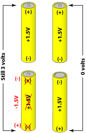
I thought of an analogy this morning on my drive to a project site. Let?s go back to the TV remote. It has 2 AA batteries connected in series with the negative terminals down and the positive terminals up, as shown to the left. The two 1.5 voltages add together to give us 3 volts total.

When we change our reference point to be at the point between those two batteries, and we use a volt meter to measure the voltages from our reference point, our volt meter will record the upper battery as having +1.5 volts, and the lower battery as having ?1.5 volts. This is shown by the Red text. So we would (could) call them out of phase (or reversed polarity).

Our point of reference has changed, but the batteries have not. This would be like crossing out the labels on the batteries an putting our own markings on it (as shown in Red Text).

You, on the other hand, are trying to redefine the battery itself and say that it is turned upside down, with its positive terminal down and the negative terminal up, and the voltage still being the positive voltage printed on the label (as shown to the right). When you add these two batteries up (i.e. connect them together) you get a total of zero volts across them.

Batteries.jpg
 
Living on the big blueberry

Living on the big blueberry

jim dungar said:
My statement "just because you can doesn't mean you should" could be used to justify choosing the reference point n in your network.

Just when you think you have learned something.:-? Actually I have, the step analysis is easier to work in the sample circuit if you use the corner.

jim dungar said:
Actually I have not been advocating a corner reference as much as I have been arguing against this specific use of 120V @180?. My point has been to keep the driving voltage source in the same direction as its current

Now are we back to talking about preferences? If you have a preference, I'll be glad to adopt it if it brings me VALUE. The corner reference brought me value...YUMMY...I'll adopt my big blueberry model to take it in.:wink: With the big blueberry, I can use any model I choose. If it is believed that one model is THE choice, show me how it brings me VALUE above a different model and I'll use it.

winnie said:
Its a matter of the notation that you are using...As you note, every voltage difference requires two points for the measurement... The two approaches are equivalent, and you can move from one representation to the other as needed for a given problem.
-Jon
Exactly. Sounds like a big blueberry man.:)

Rick Christopherson said:
When you draw a circuit diagram, there are no reference points. Those are just voltage sources stuck between labeled points. A specific or chosen reference point doesn't come into play until you start writing equations for the circuit. Two different people that have no prior knowledge of a circuit diagram should be able to solve the diagram and get the same answer, regardless what their chosen reference point is for their set of equations.
Also sounds like a big blueberry man.:)

Rick Christopherson said:
For the single resistor circuit you should have gotten:
Vbn = -115@180 = 115@0
Van = 115@0
vab = 0

For the complex circuit you should have gotten:
Vbn = -115@0 = 115@180
van = 115@0
vab = 230@0
Ooops. The math must be correct if you are going to use different models.
[edit: ...just noticed you mentioned 2 different circuits. I'll have to dig back through to see which two you might be talking about]

And for those who haven't figured it out, the big blueberry is the REAL WORLD:
BigBlueberry-NASA.jpg
 
Last edited:
mivey said:
And for those who haven't figured it out, the big blueberry is the REAL WORLD:
While your posting was rather cute, I think you jumped the gun a little bit. I can't speak for the other participants, but my discussions (and I think theirs too) have all been generic, without respect to any "preference" or "reference".

This has been the whole point of my discussion, at least. Circuit and phasor diagrams should be the same regardless what your chosen point of reference is. They should not change regardless whether they are floating in space or grounded to an 8-foot ground rod jammed into a big blueberry.

(edited for the blueberry reference :))
 
Last edited:
mivey said:
Ooops. The math must be correct if you are going to use different models.

I'm going to have to find these two circuits. You try to get a little work done and get so far behind. Why don't ya'll go log some billable hours so I can have time to catch up.:grin:
 
Rick Christopherson said:
While your posting was rather cute, I think you jumped the gun a little bit. I can't speak for the other participants, but my discussions (and I think theirs too) have all been generic, without respect to any "preference" or "reference".

This has been the whole point of my discussion, at least. Circuit and phasor diagrams should be the same regardless what your chosen point of reference is. They should not change regardless whether they are floating in space or grounded to an 8-foot ground rod.
"Jumping the gun": Can't argue that. In skimming the posts I must have missed the point.

"They should not change": I agree. I was not aware they were changing. I would say that the phasor for Vab would look different than the phasor Vba even though it is the same leg in the circuit. You can use more than one phasor diagram to represent a circuit. The circuit is the circuit and while it won't change, labeling might.
 
Rick,

I believe I have always maintained that if,

Van = Vnb = 115 @ 0, then

Vbn = 115 @ 180.

therefore, Van and Vbn are 180 degrees out of phase.

That is all there is to it.

Now go solve for the currents in teaser.doc.
 
mivey said:
"Jumping the gun": Can't argue that. In skimming the posts I must have missed the point.
I am glad you stated this :smile: , because on a couple of occasions I wanted to suggest that you go back and review this thread in its entirety, but I did not want this to sound as though I was being insulting.

This discussion is a little bit different than the previous discussions, so it might be a good idea to review it in the sequence that it has unfolded.
 
Rick Christopherson said:
I am glad you stated this :smile: , because on a couple of occasions I wanted to suggest that you go back and review this thread in its entirety, but I did not want this to sound as though I was being insulting.

This discussion is a little bit different than the previous discussions, so it might be a good idea to review it in the sequence that it has unfolded.

Don't worry, I don't offend easily, unless I'm having a bad day. There's plenty of times I say stupid stuff. While you are not "permitted" to tell me I'm stupid here without incurring "the wrath", I don't mind being corrected. Just ask my wife:grin:

Do I need to go back to a prior thread as well or can I just start here?
 
mivey said:
Do I need to go back to a prior thread as well or can I just start here?
No, this thread stands on its own. This is actually Jim's discussion, so most of us have been keeping a low profile until Jim wraps up what he has to offer.
 
rattus said:
Rick,

I believe I have always maintained that if,

Van = Vnb = 115 @ 0, then

Vbn = 115 @ 180.

therefore, Van and Vbn are 180 degrees out of phase.

That is all there is to it.

Now go solve for the currents in teaser.doc.
I believe this contradicts what you have stated previously, so I am reluctant to comment on this until a few other members have a chance to comment as well.
 
Rick Christopherson said:
I believe this contradicts what you have stated previously, so I am reluctant to comment on this until a few other members have a chance to comment as well.

There has been more than enough nit-picking on this simple matter, we don't need a rerun.
 
Status
Not open for further replies.
Top