Open Service Neutral GFCI/RCD Detector

Status
Not open for further replies.


Now, there is argument over the need for such and wether the neutral is supplied, and if there is any difference between the TT system and what the USA uses...my own instructor here has argued that the USA uses a TT system because they only supply two live and a neutral, and the ground is supplied at the home, while in the UK the ground and the neutral are supplied by the utility in the PEN conductor, and a ground rod at the home is not necessary but is a safety precaution.
again, I am just a student, but, if it was my home or my parents home then I would be trying to rewire the home using a good electrician so that every outlet had the live wires, a neutral wire, and a ground wire, using at least NMB 4 wire or is done in conduits, four wires... and I would get the neutral wire run by the electrical provider... but I am not you.


The USA uses TN-C-S or IT when supplied by utilities (with some utilities now refusing to give IT services), TT is absolutely forbidden by the NEC and always has been. The misconception comes from code requiring grounding electrodes at all services. The reasoning has more to do with power companies using a multi grounded neutral system where the neutral relies on earthing at many locations throughout.

From article 250.4 (A) (5):


(5) Effective Ground-Fault Current Path. Electrical equipment
and wiring and other electrically conductive material
likely to become energized shall be installed in a manner that
creates a low-impedance circuit facilitating the operation of the
overcurrent device or ground detector for high-impedance
grounded systems. It shall be capable of safely carrying the
maximum ground-fault current likely to be imposed on it from
any point on the wiring system where a ground fault may occur
to the electrical supply source. The earth shall not be considered
as an effective ground-fault current path.


Here is what the NEC requires and where MGN systems can be used:


(C) Multigrounded Neutral Systems. Where a multigrounded
neutral system is used, the following shall apply:

(1) The neutral conductor of a solidly grounded neutral
system shall be permitted to be grounded at more than
one point. Grounding shall be permitted at one or more
of the following locations:
a. Transformers supplying conductors to a building or
other structure
b. Underground circuits where the neutral conductor is
exposed
c. Overhead circuits installed outdoors

(2) The multigrounded neutral conductor shall be grounded
at each transformer and at other additional locations by
connection to a grounding electrode.

(3) At least one grounding electrode shall be installed and
connected to the multigrounded neutral conductor every
400 m (1300 ft).

(4) The maximum distance between any two adjacent electrodes
shall not be more than 400 m (1300 ft).

(5) In a multigrounded shielded cable system, the shielding
shall be grounded at each cable joint that is exposed to
personnel contact.


This need for grounding out on the utiltie's system ends up carrying over to the customer's service. Remember that in the UK and elsewhere the primary MV system is usually 3 wire, with the primary transformer winding in delta. Often the MV ground of the transformer is independent of the LV ground. On the other hand in the US the MV neutral, LV neutral and transformer can ground are usually all interconnected. This will without a doubt influence the code.
 
Oh, and the torrid is not wound to small because all it is doing is picking up the current from the outside of the wires.
It is not transforming any current actually but only getting enough to sense the differences

The windings are not the input wires themselves? But this illustration shows it is.
2C9AEv.jpg
 
The windings are not the input wires themselves? But this illustration shows it is.

That drawing is a reasonable schematic for understanding how the flux balancing out works.

However the 'scale' if you will of the number of turns is wrong.

The 'sense' coil will have lots of turns.

The circuit conductor 'coils' will have '1' turn, simply the conductors entering the toroid from one side and exiting on the other side, without looping around the core at all.

Take a look at this video at about 2:45 https://www.youtube.com/watch?v=P-lVtezbqrc where you can see the sense coil as a cylinder, and the circuit conductors as flat metal strips passing through its center.

Also look at 'current transformers' which are used for metering, and how they are wired.

-Jon


Say. Can the sensing be affected depending on how center is the conductor entering the toroid? What if one is nearer to the side than the other return conductor.. can it affect the performance or can the two wire be position anywhere as it enters the sense coil?
 
Say. Can the sensing be affected depending on how center is the conductor entering the toroid? What if one is nearer to the side than the other return conductor.. can it affect the performance or can the two wire be position anywhere as it enters the sense coil?

Somewhat. Position of the conductor can be considered a 'second order' effect, which will introduce error in the measurement. For residual current sensing it is a good idea to maintain symmetry of the conductors being measured so the errors cancel out.

-Jon
 
Somewhat. Position of the conductor can be considered a 'second order' effect, which will introduce error in the measurement. For residual current sensing it is a good idea to maintain symmetry of the conductors being measured so the errors cancel out.

-Jon

Since I may use dozens of this and this was installed in all outlets in many hotes. I sacrificed a unit to see if the components are ballpark and for quality check. This is the spec sheet (in 1 pdf) of the FM2141 chipset used in these 240v GFCI OEM http://www.internationalconfig.com/icc6.asp?item=74900-RCDS used by Meiji and dozens of other companies

https://www.google.com/url?sa=t&rct...fileExt=file&usg=AOvVaw1KyLU_hLlbbFdnLvtJ2Z9x


AfzgB7.jpg


Are the 2 coils at the middle the relay coils? Isn't it supposed to integrated in one unit just like the relays available elsewhere? How does the implementation of it compared to others like the Leviton, Siemens, etc. Receptacles?
Also based on the circuit diagram of the FM2141 below, where is the second coil at the middle of the diagram located above?
What is your (and others) general impression of it? Would you use dozens of this yourself at home if given the same situation where you need 240v receptacles and auto-monitoring self test is not included in it and no other 240v receptacles in the world has it?

nedL2h.jpg
 
Last edited:
Take a look at this video at about 2:45 https://www.youtube.com/watch?v=P-lVtezbqrc where you can see the sense coil as a cylinder, and the circuit conductors as flat metal strips passing through its center.

-Jon

Good one.....that;s been one of my habits since i was a wee lad

i used to haul old tv's , etc , out of the trash

tankfully there was no internet ,or phone cameras ,when i learnt 'capacitor 101'....:ashamed1: ~RJ~
 
Now I'm getting it why no one else has much experience on these 2-pole 240v GFCI breakers. Because you only use it on tubs and spas.


It doesn't have any EGC (Equipment Grounding Conductor). All appliances don't have EGC.

Notice the flooring below. It's made of porcelain or marble. Are porcelain or marble insulator or can these conduct electricity (in ground fault)?
Tersh,
Ah. . . we do eat rice :)


There are about 200 rice-based dishes and available in regular and ethnic restaurants in Southern Cal. The Thai Khao Phat, Italian Rizzoto, Indian Bhaat, the Spanish Paella and of course the Philippine Congee. A real tasty, watery dish with the look of wheat cereal floating in milk. But the congee doesn't have milk. . .it is watery though. :)


And we grow rice in California, Texas and Louisiana.


Now back to the topic.
If neither of the secondary wire is grounded (aka floating), there would be no stray current to ground. . .and you or your mama can touch either of the line all day long and no one will get shocked.


We'll keep this simple without referring to capacitive or inductive coupling flubdub.


To demonstrate this “floating” lines—look at those (birds) crows especially-- perched in a single file along high voltage lines that look like they are conversing and having a good time and planning for the next murder. (murder is the term for a gathering of crows). So, no implied maleficence here. As long as they're in contact with only one wire they are safe. You will also wonder why all of them are facing one direction—but that is not important for now. LOL


Ungrounded system is totally accepted wiring practice. In some installations, there is no other option. If you have ever worked as a shipboard electrician you will notice that none of its power system is grounded or connected to the hull.
If no conductor is grounded (as in neutral ) having a ground fault on one hot leg will not cause a breaker to trip and equipment will keep operating. Ask a friend who worked in the NAVY who is an electrician (not those guys guiding those F-35s landing on the deck or he'll tell you “get out of my way smart a**.”


The philosophy behind the idea of ungrounded system that was decided upon by the Marine Architect / Engineer lies on the priority of keeping the seagoing vessel afloat.


Keeping the vessel above water that is miles away from land takes priority above everything else. Safety of the personnel and keeping them from the hazard of electricution has less importance in contrary to NEC. As far as the designing marine engineer is concerned, you can sail away with your NEC until you disappear into the horizon.:)


They don't need NEC at sea.


Click on this, if your machine doesn't make the link try copying it to your search engine.


https://www.brighthubengineering.com/marine-engines-machinery/38231-electrical-grounding-on-ships/


I'm not saying human life is not important on a ship. . . so, hold your guillotine for a minute.


The complexity of modern guidance electronic system is mind-boggling. Communication is crucial along with the power sources and other equipment that keep the vessel afloat.


Now, someone might ask—how does the ship commiserate with the ungrounded rice cooker.


Well...the priority of the shipbuilder and the homeowner lie on each other's judgment that would provide the most reward.


The shipbuilder would be able to save the ship while the homeowner would not have to worry about GFCI— and cook as many bowls of rice as he can without having to worry getting shocked.


The prevailing syllogism is: if the ship sinks all souls aboard would perish. (Barring those who are able to grab a dinghy.)


So, its better to save the ship than losing someone getting fried because of carelessness, stupidity or ignorance.


In addition. . . . most modern home appliances that have heating element don't need grounding. It doesn't matter whether they are 230 volts or 120 volts.


The old-school heater designs that have those exposed nichrome heating elements are suspended with stand-off and mica to separate the element from the metal case. As the nichrome wire stretches when heated (as most metals do) they tend to get dislodged from its support that could either short out or make contact with the case. This is when you need grounding.


However, the modern nichrome alloy heating elements are imbedded in ceramics or the other design where the heater resides in a quartz envelope. No exposed live parts. So, no need for grounding either.


The new rice cookers are made this way too.


Think of the quartz lamp. You touch the bulb and you don't shocked. Ceramics and quartz have high melting point and perfect insulators.
Those 230 volt 2P GFI in US households are usually built-in to the appliance male plug. Most hairdryers have them too. But you can buy the 230 volt 2P CB at HD. Since most of those previously occupied homes have shared neutral-- it becomes problematic when you use a 230 volt 2P GFI breaker. It needs a dedicated neutral (white) from the panel to the outlet.


The plug-installed GFI is the best alternative. This is common in those thru-the-wall room airconditioner that is over 12000BTU. They are not suitable to be plugged-in with other “garden variety” appliances that are protected by 20 A 1P CB.
Because of the higher power demand, they need 230 volts power. You would still need a dedicated 230 volts 2P branch circuit though.


Have a happy rice cooking.
 

….


In addition. . . . most modern home appliances that have heating element don't need grounding. It doesn't matter whether they are 230 volts or 120 volts.


The old-school heater designs that have those exposed nichrome heating elements are suspended with stand-off and mica to separate the element from the metal case. As the nichrome wire stretches when heated (as most metals do) they tend to get dislodged from its support that could either short out or make contact with the case. This is when you need grounding.


However, the modern nichrome alloy heating elements are imbedded in ceramics or the other design where the heater resides in a quartz envelope. No exposed live parts. So, no need for grounding either.


The new rice cookers are made this way too.


Think of the quartz lamp. You touch the bulb and you don't shocked. Ceramics and quartz have high melting point and perfect insulators.
Those 230 volt 2P GFI in US households are usually built-in to the appliance male plug. Most hairdryers have them too. But you can buy the 230 volt 2P CB at HD. Since most of those previously occupied homes have shared neutral-- it becomes problematic when you use a 230 volt 2P GFI breaker. It needs a dedicated neutral (white) from the panel to the outlet.


The plug-installed GFI is the best alternative. This is common in those thru-the-wall room airconditioner that is over 12000BTU. They are not suitable to be plugged-in with other “garden variety” appliances that are protected by 20 A 1P CB.
Because of the higher power demand, they need 230 volts power. You would still need a dedicated 230 volts 2P branch circuit though.


Have a happy rice cooking.


Please tell me. Is it normal for any appliance to leak 1mA?

One problem with the concept of Siemens GFCI 2-pole 240v breaker is it's suppose to be used for the tubs and spa. Meaning for only one circuit or appliance. Whereas my plan of putting it in the Siemens subpanel is for one 30A GFCI breaker to drive the outlets of an entire room (with 5 appliances) and I'm afraid the 5mA may be too sensitive (the Europe uses 30mA for multiple circuits precisely to avoid the tripping). Is this reasoning correct? Or shouldn't any appliance leak even 1mA?
 
One millionth of an amp tersh?

I'd wager that probably exists in the earth ,maybe more so proximal to poco infastructure

but i digress, everything is focused here on a toroid, the chief component of all low voltage protective ocpd's.

were one to design the optimum electrical panel with them, i'd opt for descending order of ma from main /sub main/individual ocpd

jmho ~RJ~
 
Please tell me. Is it normal for any appliance to leak 1mA?

One problem with the concept of Siemens GFCI 2-pole 240v breaker is it's suppose to be used for the tubs and spa. Meaning for only one circuit or appliance. Whereas. . . my plan of putting it in the Siemens subpanel is for one 30A GFCI breaker to drive the outlets of an entire room (with 5 appliances) and I'm afraid the 5mA may be too sensitive (the Europe uses 30mA for multiple circuits precisely to avoid the tripping). Is this reasoning correct? Or shouldn't any appliance leak even 1mA?


Tersh,

Your GFCI (as you said) was designed specifically for tubs and spa. As such, it may have been designed to operate within a threshold that will offer optimal protection.

I have a spa and nobody has died of electricution.

It has no GFCI-- just generic 2P circuit breakers. The heater is natural gas and the air bubble motor and circ pump are 240 volts--mounted away from the tub. All control buttons mounted at the edge of the tub within arms reach are activated by pneumatic latching relays. . .so, no wires carrying line potential are around the tub. Except the 12 volts for lighting.
Just quarter inch pneumatic tubing are extending from the tub to the control panel to activate/deactivate the motor starters..

This has been like this for almost 30 years.

Since there were no GFCI's at the time when this was built, I used a 12volt underwater filament type bulb normally used on swimming pools for lighting below water level. This is powered by a two winding 120/12v Xfmr. These are working up to this writing. I drain it regularly and I check the water PH balance to protect metal components.

Your plan to use the 2P Siemens GFCI CB to provide power for appliances (not for spa) would be considered outside the design parameters. . . and not guaranteed to work as designed. It may work, but then again, it may not.

One thing that I doubt whether it will function satisfactorily is the fact that those appliances that will be plugged in could have been manufactured with a plethora of varying standards. Some Chinese, Japanese,European and US.

US appliances may have been manufactured that adhere to ANSI, ASTM or the more stringent MIL-SPECS. Can't guarantee those from China.

The insulating property of each appliance from different manufacturers could have different dielectric properties. For example the insulating property used in magnet wires for motors.

Different dielectric insulating property may allow certain leakage which result in different levels of current in milliamps.

So, what would be the best approach to rein in this aberrant behavior would remain elusive in my book.

Have a good day.

BTW: All the above installations passed with flying colors from local AHJ.


Tersh, don’t get hung up on my it. The gfci works on multiple appliances at one time normally... you could put individual gfci outlets in your home using pigtail wiring, but at the same time, from a cost perspective, one breaker or gfci outlet can protect several outlets. So far, the makers and the code have not yet specified the number of outlets covered by one gfci...
in the UK, the RCD covers more than one circuit, each containing many outlets... in fact, the outlet number is not specified, only the square meters covered by the circuit... it is possible to put a thousand outlets on each breaker, and six breakers on each RCD ina british home and it would be covered as safe.

in the USA NEC there is also no limit to the number of outlets per circuit breaker in a home, unless it has an appliance that uses more than a certain amount of the power of the circuit... then it should be switched to a designated circuit...

thus, from design standards in both countries, the concern is not as necessary for each single appliance but for the overall condition of your wiring, grounding, etc...

You forgot to think that the GFCI is 5mA and not 30mA. You could drive many outlets with the 30mA RCD.. but with a single 5mA GFCI. Won't it trip a lot if you have 5 outlets connected to it?
 
Tersh,

Your GFCI (as you said) was designed specifically for tubs and spa. As such, it may have been designed to operate within a threshold that will offer optimal protection.

I have a spa and nobody has died of electricution.

It has no GFCI-- just generic 2P circuit breakers. The heater is natural gas and the air bubble motor and circ pump are 240 volts--mounted away from the tub. All control buttons mounted at the edge of the tub within arms reach are activated by pneumatic latching relays. . .so, no wires carrying line potential are around the tub. Except the 12 volts for lighting.
Just quarter inch pneumatic tubing are extending from the tub to the control panel to activate/deactivate the motor starters..

This has been like this for almost 30 years.

Since there were no GFCI's at the time when this was built, I used a 12volt underwater filament type bulb normally used on swimming pools for lighting below water level. This is powered by a two winding 120/12v Xfmr. These are working up to this writing. I drain it regularly and I check the water PH balance to protect metal components.

Your plan to use the 2P Siemens GFCI CB to provide power for appliances (not for spa) would be considered outside the design parameters. . . and not guaranteed to work as designed. It may work, but then again, it may not.

One thing that I doubt whether it will function satisfactorily is the fact that those appliances that will be plugged in could have been manufactured with a plethora of varying standards. Some Chinese, Japanese,European and US.

US appliances may have been manufactured that adhere to ANSI, ASTM or the more stringent MIL-SPECS. Can't guarantee those from China.

The insulating property of each appliance from different manufacturers could have different dielectric properties. For example the insulating property used in magnet wires for motors.

Different dielectric insulating property may allow certain leakage which result in different levels of current in milliamps.

So, what would be the best approach to rein in this aberrant behavior would remain elusive in my book.

Have a good day.

BTW: All the above installations passed with flying colors from local AHJ.


I already have 6 pcs of Siemens 2-pole 240v GFCI breakers (5mA) just waiting for Siemens to confirm it's not counterfeit.

S4AKXV.jpg


To ensure they won't trip. So they must be used for one appliance each, for example.. existing bathroom multipoint heater circuit which can't be used on GFCI receptacles because of the huge 6000w power.. as well as washing machine and water pumps or aircons too.

I'd like to know if you can use a 30mA RCD before the Siemens panel housing those 6 pcs of 5mA GFCI breakers. Assume each GFCI breaker reach 5mA. Total is 5mAx6= 30mA. But if that happens. All the 6 GFCI breakers would trip. This means 30mA would be enough for the RCD to be put before the Siemens panel just to protect it from the bus melt melting the plastic basepan and touching the panel chassis (or feeder wire touching the chasses) all accidentally worse case scenario of course? The Siemens panel would be connected to the local electrode ground rod so what I have is a TT system just like Europe (without directly conductor path to the transformer due to difficulty in getting neighbors approval to demolish the driveway just to add the ground wire).
 
I'm looking for a meter that can detect leakage current that is based on the sense coil technology in GFCI. So imagine a plug-in meter where you can plug to existing outlet or extension cord then your appliance plugged to the device and can show whether it's leaking 1mA to 50mA leakage current.


Anyone has encountered such device? I want to study how different appliance leaks to study nuisance leaking in GFCI application.


Btw.. I'm decided to use 30mA RCD before the Siemens panel with 6 pcs of Siemens GFCI breakers (5mA) not only to protect the panel chassis from sorted hot wire. But as back up in case the Siemens breakers got defective. Remember that if you suddenly cut the power supply to the circuit of the Siemens GFCI, it won't open the breaker, but stays close. So the RCD with 30mA will be backup and perfect for it.

I'm looking for the most advanced 100A RCD (30mA tripping) brand and model in the planet. One that can even show in display the leakage current itself (like showing 3mA or 8mA, etc.). Can anyone share what is such model? Ok if it doesn't have built-in leakage current meter and display. I could use a separate meter for this. But the 30mA RCD must have the most complete features that can exist in RCD.

I'm doing all this not just for personal but to understand and study and share the knowledge with local electrical engineers to protect millions of homes in the country without any local electrode and no direct conductor to utility transformer. This is less than a TT system, perhaps an HT system (Home Terra), not Terra Terra. First thing would be to conduct study what kind of appliance can leak and how much (with the sense coil based leakage current meter), then share the list of appliances with ambient leakage current values so others can know what device to use, etc. Will also recommend to government and Code makers to be strict in implementary at least TT (if they can never put conductor direct to utility transformer without tearing apart the whole house) setup to be sure the RCD or GFCI will trip.
 
I already have 6 pcs of Siemens 2-pole 240v GFCI breakers (5mA) just waiting for Siemens to confirm it's not counterfeit.

S4AKXV.jpg


To ensure they won't trip. So they must be used for one appliance each, for example.. existing bathroom multipoint heater circuit which can't be used on GFCI receptacles because of the huge 6000w power.. as well as washing machine and water pumps or aircons too.

I'd like to know if you can use a 30mA RCD before the Siemens panel housing those 6 pcs of 5mA GFCI breakers. Assume each GFCI breaker reach 5mA. Total is 5mAx6= 30mA. But if that happens. All the 6 GFCI breakers would trip. This means 30mA would be enough for the RCD to be put before the Siemens panel just to protect it from the bus melt melting the plastic basepan and touching the panel chassis (or feeder wire touching the chasses) all accidentally worse case scenario of course? The Siemens panel would be connected to the local electrode ground rod so what I have is a TT system just like Europe (without directly conductor path to the transformer due to difficulty in getting neighbors approval to demolish the driveway just to add the ground wire).

30ma is the max threshold, it may trip below that. Ie, 25ma.
 
30ma is the max threshold, it may trip below that. Ie, 25ma.

bujeUY.jpg


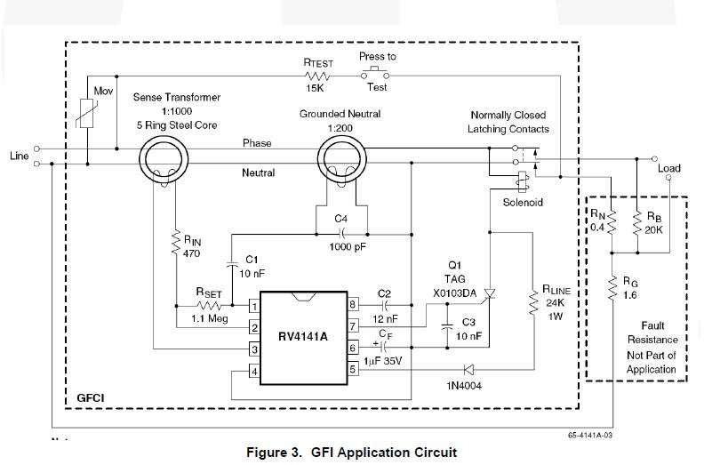
This is the circuit diagram of the previous Leviton GFCI receptable without auto-monitoring self test.

Do you (or others) know whether the current coming out of the sense transformer or sense coil is directly the differential current of say 3mA? Or does it come out much lesser than that (for example 3 uA) and the chipset has to amplify it to become 3mA?

Because if the leakage current existing the sense coil is actual.. then they can simply put an ammeter before the chipset and lcd display to output the actual leakage current.
 
Tersh, do you have a clamp meter? If so then basically you are using a meter similar to what they use in the circuit of a GFCI or RCD... they just use a smaller, dedicated circuit...
 
Tersh, do you have a clamp meter? If so then basically you are using a meter similar to what they use in the circuit of a GFCI or RCD... they just use a smaller, dedicated circuit...

I found in the attic a clamp meter I only used a few times. It has 1mA resolution. If your appliance has leakage of 3mA. Can you really measure it with that? When I clamp the flat cord wire a while ago the reading is 0 (I know you need to separate the hot and neutral to avoid field cancellation to get a reading in either). I don't know if it is zero when wire joined because the clamp meter is accurate not detecting any leakage or I don't know if the meter is just not accurate :)


I think there might be plug in clamp meter that can function as accurate sense coil device to measure leakage current? Have you heard of one? It's difficult to hold steady with the clampmeter.
 
30ma is the max threshold, it may trip below that. Ie, 25ma.

I recently tested one of the RCD's in my flat (apartment) board that fed the ring circuit, it tripped at 17mA. Supposedly too low but I'm more than happy with the result.

We can get 5mA RCD's but they are dammed expensive. I used them for my photographic darkroom, electricity, water, chemicals and wet hands aren't a good combination, I've an aversion to electric shocks after getting 10kV up my arm. The shock didn't do the damage, hitting the concrete wall backwards knocked me out.
 
Status
Not open for further replies.
Top