Why is residential wiring known as single phase?

Status
Not open for further replies.

Rick Christopherson

Senior Member
Sorry Posted under wrong poster
Oh, and I was just thinking about this....why didn't he say the same thing to me? :lol:

Thats really going to hurt the Ego of all the want to be Electricians.
That may hurt some egos, but it wasn't the intention. Look at it from an unrelated perspective. Do you think a plumber has even heard of a Bernoulli equation, let alone contemplated one as he is sweating an elbow? Heck No! He doesn't need to know how the fluid flows and transitions through that elbow and pipe. He only needs to know how to sweat that joint without it leaking. On the other hand, the engineer that does understand the fluid flow, most likely couldn't sweat a leak-tight joint if his life depended on it. The same is true in electrical systems. The electrician doesn't need to understand why a MWBC needs to use opposing legs, he just needs to know that they do. The engineer that understand the concept of the MWBC won't necessarily know how to rope a house....<and he runs off to put on his cowboy boots and hat to wrangle that task. :lol:>
 

Besoeker

Senior Member
Location
UK
120210-0648 EST

Besoeker:

A reference for the usage of 6 phase from the use of 3 center tapped transformers in a 3 phase system is:

"Theory and Application of Industrial Electronics", Cage and Bashe, McGraw-Hill, 1951. See page 10 for several rectifier connections, including six-phase half-wave using three center tapped secondaries.

.
Thanks gar.
I don't have the book but I'm moderately familiar with the six-phase half-wave arrangement. We've made quite a few.
My point was that tocall it hexaphase or six phase you need to consider each of the three centre-tapped windings as two phases. And each is the same configuration as a 120-0-120 arrangement. For that to be called single phase is the equivalent of calling hexaphase three phase.
 

jim dungar

Moderator
Staff member
Location
Wisconsin
Occupation
PE (Retired) - Power Systems
...
My point was that tocall it hexaphase or six phase you need to consider each of the three centre-tapped windings as two phases. And ...

Sorry shooting from the hip, would have sidetracked the discussion.
 
Last edited:

mivey

Senior Member
No I don't. I only have to establish that the phase value of the voltage functions is the same. Which I have demonstrated many ways, many times. Although no one seems to have noticed it until recently.
Perhaps because it is not correct.

In my original entry into this morass I said, "...phase is not an electrical concept; it has nothing to do with Volts, Amps, polarity, amplitude, Ohm?s Law, Kirchhoff?s Laws, Ampere?s Law, Lenz?s Law, Coulomb?s Law, or any other ?law? derivable from Maxwell?s equations." - It's MATH.

Write the voltage function correctly for ANY arbitray set of points you desire and, for a properly installed residential 120/240V system, the phase value for each and every voltage function will ultimately resolve to Φ(t)= wt+Φ. It's simple trig/algebra.
If you might recall, the "Φ" in the "wt+Φ" comes from solving the differential equation for an oscillating system. For the phase, you wind up with the time-dependent portion that also has a frequency component and you also have the "Φ" portion that gives the other part of the differential equation solution that yields the initial conditions.

What you have done is taken the "Φ" constant and broken it into "Φ1+Φ2". Then you took part of the initial condition and moved it outside the parentheses and said "hey look: Φ and Φ1 are the same thing if we ignore the initial condition related to Φ2"

All you have shown is that you can take two odd signals (recall from signal analysis that an even signal has x(-t) = x(t) and an odd signal has x(-t) = -x(t) ) with an initial 180? phase displacement (i.e. having "Φ" and "Φ+180?"), shift one by 180? voil?: you get "Φ" in the function for the original signal and the shifted signal. No surprises since that is what we already know without the math derivation.


BTW this is consistent with "classic" two-phase systems where there will be two characteristic phase values: wt+Φ, wt+Φ +90o and conventional three-phase systems where the characteristic phase values can ultimately be resolved to: wt+Φ, wt+Φ+60o and wt+Φ+120o.

Nope, I meant what I said. I'm discussing the phase value of voltage functions, not the voltage functions themselves.

Φ(t) = wt+Φ+180o ultimately resoves to -Φ(t) = wt+Φ.
Φ(t) = wt+Φ+240o ultimately resoves to -Φ(t) = wt+Φ + 60o and
Φ(t) = wt+Φ+300o
ultimately resoves to -Φ(t) = wt+Φ +120o.

The characteristic phase values are still wt+Φ, wt+Φ+60o and wt+Φ+120o.
Just more of the same math mistake.
 

mivey

Senior Member
Is for hexaphase which you get from three centre-tapped windings, an arrangement commonly used on low voltage high current rectifiers.
Agreed. Another example is a four-phase system using center taps which is what we label as a two-phase system or quadrature system (5-wire 2-phase). Labels are one thing but a system's physics another, even if they are related. The labels are simply not complete system descriptions.
 

Besoeker

Senior Member
Location
UK
Sorry shooting from the hip, would have sidetracked the discussion.

Actually, I think it is quite pertinent to the original post and ensuing discussion:

Sixphasevtwophase01.jpg


Two circuit arrangements. The first, A, is that arrangement commonly in use in (US) residential wiring. The elements of A are replicated as part of B.
Now, with Arrangement B being called hexaphase, isn't there a logical argument based on that for calling Arrangement A duo-phase?
 

rattus

Senior Member
Referemce

Referemce

Could someone please post a valid reference which proves the statement, "an inversion is not equivalent to a phase shift"? Start a new thread if this one is closed.
 

mivey

Senior Member
I don't propose establishing the phase relationships for a three-phase. That requires building a reference system far beyond this discussion. Describe the fundamental fault. It's not faulty just cause you disagree.
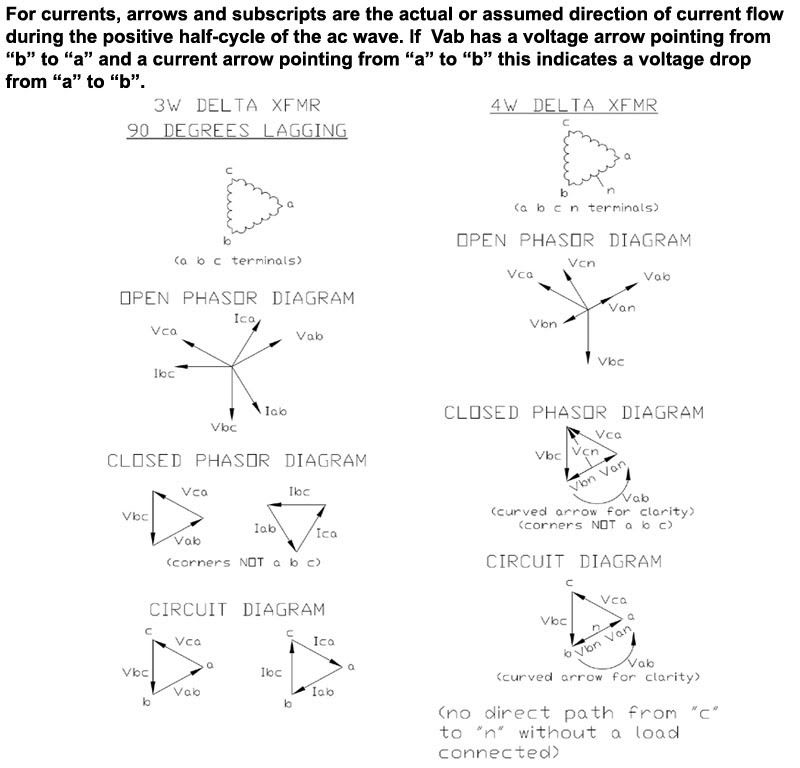
Sorry, thought I was clear. The premise that the physical location of the voltage reference must also coincide with the physical location of the other voltage is the fundamental fault. That is not the case and anyone who has ever made a phasor diagram should know this. It might also be worth mentioning, as I have in the past, that a phasor diagram and circuit diagram are not the same thing either so you should see the disconnect between the physical layout and the related physical angles vs the voltage phasors with the related phasor angles.

See here:

phasorvscircuitdiagram.jpg
 

Rick Christopherson

Senior Member
Could someone please post a valid reference which proves the statement, "an inversion is not equivalent to a phase shift"? Start a new thread if this one is closed.
Yeah, I've said it several times.

Put a noise artifact on your primary. Let's say at the top of the positive peak, just for simple reference, and repeating once per cycle so it only appears in the positive peak.

Now look at your scope for the secondary. This noise will appear in both waveforms. If there was a phase shift, this noise artifact would appear in the positive peak of both waveforms. If it is an inversion, then the noise artifact will appear in the positive peak of one waveform and the negative peak of the other wave form. The latter is what we already know will be seen.
 

mivey

Senior Member
This is the reason why I have previously brought up the concept of a noise artifact on the sine wave. If the two signals were truly out of phase, this noise artifact would also appear out of phase. Instead, a noise artifact would show that the two signals are in fact inversions, not phase shifts. That's the difference between "appears" versus "are" out of phase.
Depends on the noise doesn't it? Apply the brake or stick a screwdriver in the drive on a multi-phase generator and look at the noise artifact appear on each signal at the same time.
 

K8MHZ

Senior Member
Location
Michigan. It's a beautiful peninsula, I've looked
Occupation
Electrician
Actually, I think it is quite pertinent to the original post and ensuing discussion:

Sixphasevtwophase01.jpg


Two circuit arrangements. The first, A, is that arrangement commonly in use in (US) residential wiring. The elements of A are replicated as part of B.
Now, with Arrangement B being called hexaphase, isn't there a logical argument based on that for calling Arrangement A duo-phase?

I don't know if what I noticed makes a difference or not, but looking at the windings of a Wye transformer, looking out from the neutral, they all turn the same way, and they are all separate windings, not a single winding that is center tapped.

Your hexaphase drawing does not have all the windings going the same way (I mean like clockwise) as looking out from the neutral. I believe you drew it that way to show some sort of relationship between hexaphase and single phase. If you drew it like a 3 phase wye, their would be no similarity between a pair of secondary coils in a hex system and the single secondary coil in a single phase center tapped system.
 

rattus

Senior Member
Yeah, I've said it several times.

Put a noise artifact on your primary. Let's say at the top of the positive peak, just for simple reference, and repeating once per cycle so it only appears in the positive peak.

Now look at your scope for the secondary. This noise will appear in both waveforms. If there was a phase shift, this noise artifact would appear in the positive peak of both waveforms. If it is an inversion, then the noise artifact will appear in the positive peak of one waveform and the negative peak of the other wave form. The latter is what we already know will be seen.

That is not a valid reference. There is no noise in an ideal waveform which we must assume when we assign a phase angle to a waveform. Please cite a valid reference.
 

mivey

Senior Member
And Rbalex did a great job with the math in his postings.
I liked the idea, and I appreciated the different viewpoint, but the math was wrong.

Two different architectures under ideal circumstances can easily resolve using the same mathematics.
If you don't mind ignoring some of the math.

Two different architectures can display on an oscilloscope identically. Rick, myself, and others have pointed out that running the leads from left to right for one leg, and right to left for the other leg, is not correct.
Just opinions.

Rick challenged them to add noise to illustrate this.
"Time shift" and "phase shift" are used in multiple ways so to make this comparison you have to have agreed-upon definitions, which seems to be a problem.

I've tried to get them to maintain a common reference frame.
No basis for that whatsoever.

Rbalex has glazed their eyes with phase calculations.
Bad math does not a glaze make.

Jim has fended numerous misconceptions.
Definitely a moving target. Sometimes I agree with Jim, sometimes not. The best I can tell it is a preference and terminology difference.
 

jim dungar

Moderator
Staff member
Location
Wisconsin
Occupation
PE (Retired) - Power Systems
I don't know if what I noticed makes a difference or not, but looking at the windings of a Wye transformer, looking out from the neutral, they all turn the same way, and they are all separate windings, not a single winding that is center tapped.

I have mentioned this previously, post #193. A center-tapped winding has more in common with a delta transformer connection, than it does with a wye. Physically, X1->X2+X1->X2 is not the same as X1->X2+X2->X1, even though both have a neutral point.

i don't believe any one commented on the question I asked:
"Based on this, why shouldn't a single phase series connection be solved the same as that of an open delta? "
 
Last edited:

K8MHZ

Senior Member
Location
Michigan. It's a beautiful peninsula, I've looked
Occupation
Electrician
I have mentioned this previously. A center-tapped winding has more in common with a delta transfromer connection, than it does with a wye.
Physically, X1->X2+X1->X2 is not the same as X1->X2+X2->X1, even though both have a neutral point.

Here is what I was trying to get at:

hexsm.jpg

Note the direction of the six windings vs. the direction of the single winding in a single phase system.

What effect does swapping the direction of the windings have on the output of a transformer?
 
Status
Not open for further replies.
Top