Just to clarify.

Status
Not open for further replies.
Mivey,

I believe that what Rick is pointing out is that since current is defined as the charge moving past a point in a given amount of time, a current probe that is somehow connected to both the point under test and the neutral point is a strange thing.

Voltage is measured between two nodes; so you can pick the neutral as a reference and then measure the voltage at any other node. You are describing your current probe as if it worked in the same way as a voltage probe.

However I think I understand what you mean to say. When you place your current probe on the wire, or model the current flowing through the wire to solve an example, there are two possible orientations or 'senses' that you can use. What you are saying is that the sense of the current measurement/value must match the sense of the voltage measurement/value that it is being associated with.

If you select your voltage reference such that the 'sense' of some of your voltage values is reversed, then to determine the power suppled or consumed at each component, you need to appropriately change the 'sense' of your current measurement.

If the voltage measurement is from N to A, then the sense of the current measurement must similarly point along the conductor from N to A, even though the current measurement itself is at a single point between N and A. If the voltage measurement is from A to N, then the sense of the current measurement must point from A to N, again at a single point between A and N.

Jon
 
mivey said:
When rattus was describing V1 & V2 as being "out of phase" across the neutral, that is fine with me, let's help him describe it.
As I have stated repeatedly, I do not have a problem with anyone wanting to say this as a matter of convenience or preference. When you are staring a load center in the eye, this is the description that makes the most sense. However, when you put it down on paper to do a circuit analysis, then you need to add the minus sign that Rattus claims does not exists. Without the minus sign, you violate one or both of Kirchoff's laws. (continued below).

mivey said:
This is what you would see on an oscope with the neutral as the common point. Still fine with me, let's help him do that without "violating" any laws.
The minus sign that Rattus wants to ignore is built-in to the probes of the oscilloscope--one probe is labeled positive, and the other is labeled negative. When you reverse these probes, you interject the missing minus sign into your measurement.

Consider this: Would you put the oscilloscope probes across a battery with the Red lead on negative and the Black lead on positive, and then claim that the battery's voltage was -1.5 volts? No, you know that you have the probes reversed, and you automatically add the minus sign accordingly. It is OK to say that you measured -1.5 volts across the battery, but it is not OK to call the battery a -1.5 volt battery. Doing the latter redefines the actual battery, not just your point of reference for the battery.
 
mivey said:
... The north pole, "coming vs going", etc was my attempt at trying to give a physical world example of the current shift. It would seem I have failed miserably so far.
I wouldn't use the therm, "failed miserably". I was trying to fine a humorous way to say, "We aren't measuring airpanes or electrons and we aren't at the North Pole - well, okay, I am, but that doesn't count.":)

carl
 
jim dungar said:
...First everyone seems to be misapplying Kirchhoff to the single current two node example. ...
Whoops, sloppy me. I wonder how many years I have been saying this. Thanks for prompting me look it up and remind myself what I learned 40 years ago. I really did understand the difference between Kirchoff's laws, Norton equivalent, and Thevenin equivalent - I promise:roll:

carl

Kirchhoff's Current Law
At any instant the sum of all the currents flowing into any circuit node is equal to the sum of all the currents flowing out of that node:
SIin = SIout

Similarly, at any instant the algebraic sum of all the currents at any circuit node is zero:
SI = 0

Kirchhoff's Voltage Law
At any instant the sum of all the voltage sources in any closed circuit is equal to the sum of all the voltage drops in that circuit:
SE = SIZ

Similarly, at any instant the algebraic sum of all the voltages around any closed circuit is zero:
SE - SIZ = 0

ThŽvenin's Theorem

Any linear voltage network which may be viewed from two terminals can be replaced by a voltage-source equivalent circuit comprising a single voltage source E and a single series impedance Z. The voltage E is the open-circuit voltage between the two terminals and the impedance Z is the impedance of the network viewed from the terminals with all voltage sources replaced by their internal impedances.

Norton's Theorem

Any linear current network which may be viewed from two terminals can be replaced by a current-source equivalent circuit comprising a single current source I and a single shunt admittance Y. The current I is the short-circuit current between the two terminals and the admittance Y is the admittance of the network viewed from the terminals with all current sources replaced by their internal admittances.
 
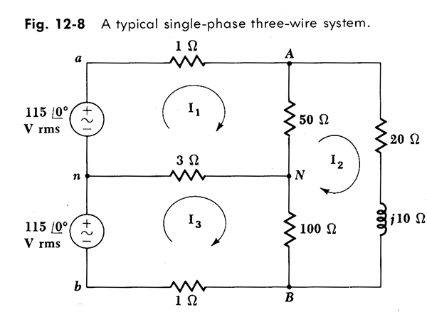
To make this distinction between an absolute value and a referenced value more clear, consider the following (using the diagram below, and ignore the inductor if you wish because it is not important to this point):

Without even doing any lengthy circuit analysis, we all know that the current flowing through the 100 ohm resistor (between points N and B) is flowing from top-to-bottom. However, we have defined I2 to be flowing clockwise, So if I asked you, "what is the current from N-to-B with respect to I2", your answer would be some negative multiple of I2.

We have defined I2 to be flowing from B-to-N, so when we calculate the actual current flowing through this resistor, the answer will be negative (with respect to I2) because the actual current is flowing opposite to what we "assumed" when we started the circuit analysis.

Conversely, by yours and Rattus' methodology, you would indicate this current as being positive, and therefore flowing from B-to-N, which opposes the actual current.

By the way, I have not solved this circuit, but I did stay at a Holiday Inn last night....Oh, wait...I meant to say that I Cheated, and looked back at the text book. For those that are curious I3 = 10.4@-21.8 and I2 = 9.39@-24.5:grin:

3-wire-scan.jpg
 
winnie said:
I'd say that you were using two different ways of accounting for current. ...
I'm not seeing this. You may have to explain this some more

winnie said:
... 1) You look at the current following closed circuit paths. In the case of a single loop, the current must be the same everywhere, and thus in your example i = 10<0 A. ...
Yes

winnie said:
... 2) You look at the current entering each _node_. Since each node has two paths into it (for a single loop), there are _two_ currents that must sum to zero. In your example circuit, these two currents are 10<0A and 10<180A. ...
Her's where I'm stalled. Take a look at the attachment

Figure 1: The current is the same anywhere in the circuit i = 10<0

Figure 2: The current is the same anywhere in the circuit i = 10<0. If I had put an N mark between the two sources, the phase angle of the current doesn't change a bit.

Figure 3: Adding the "N" point and wire didn't change a thing. The current through the resistors is still i = 10<0. The current through the sources is still i = 10<0

I'm not getting the "two different ways of accounting for current"


carl
 
coulter said:
I really did understand the difference between Kirchoff's laws, Norton equivalent, and Thevenin equivalent - I promise:roll:
Ya Know what? I thought I was over the trauma of the years of education I suffered, and out of the blue you had to drag Norton and Thevenin back into my memory. I hated these two schmucks when I was in college, and I still hate them; and now you had to go and remind me that they still exist all over again?:mad: My life would have been just fine not hearing these two names ever again....Thank you very much!:mad: :D
 
orientations

orientations

winnie said:
..a current probe that is somehow connected to both the point under test and the neutral point is a strange thing
Agreed. It was the only thing I could think of at the time.

As for orientation or "sense". Maybe it would have been better to say something like (I hope I don't mess this up): "When we take a current measurement RELATIVE to the neutral point, we will place our left foot on the neutral point, our right foot on the wire crossing the neutral, then reach down with our clamp meter and measure the current, being sure the clamp meter always remains consistently oriented with our body".

winnie said:
...What you are saying is that the sense of the current measurement/value must match the sense of the voltage measurement/value that it is being associated with...
Yes
 
mivey said:
Quote:
Originally Posted by winnie
...What you are saying is that the sense of the current measurement/value must match the sense of the voltage measurement/value that it is being associated with...

Yes

Wow, this sounds a whole lot like my position that the resistive current through a source should be in same direction as the driving voltage. See post #1.
 
Rick Christopherson said:
Like Rattus, you have lost sight of the minus sign that must be present.

Yes. This entire discussion is about a missing minus sign!
I haven't seen evidence yet that any participant here doesn't know how to analyze a circuit. Granted someone might make a mistake when making a particular calculation but who among us does not do that from time to time?

Given the level of knowledge indicated by the postings here, and the amount of time spent talking about it, I just can't seem to make the leap of faith it takes to draw the conclusion that we are arguing about a negative sign.

Maybe that is why I keep trying to dig some kernal of understanding or perspective from this thread. Somebody somewhere has a way of looking at something that is clear in their mind but they can't seem to express it to someone else.

Rick, you may be right, but I just find it incredibly hard to believe.

[edit: spelling]
 
coulter said:
I'm not getting the "two different ways of accounting for current"

These are just two different ways of describing the exact same thing, thus two different ways of doing the math. The physics is exactly the same.

Below is for a simple series circuit; both approaches can be generalized for parallel paths.

1) One way is to consider the _entire_ circuit as a loop. The rule is that the _same_ current must flow in the entire loop. You can just go around the loop in a clockwise fashion, and count up the various voltages (in a clockwise fashion), and keep the same current value everywhere.

2) The other ways is to consider the circuit as a set of connected nodes. The rule is that the sum of all currents flowing into a node is _zero_.

Now clearly approach 2 implies that the same current must flow _out_ of each node as flows _in_ to each node, thus implying approach 1.

If you use approach 2, then you _must_ consider that the current flowing into each node from the left is exactly the inverse of the current flowing _into_ the node from the right.

The 'sum the current into each node' approach is helpful when you have many parallel paths. It is simply extra work when you have a simple circuit.

-Jon
 
mivey said:
Given the level of knowledge indicated by the postings here, and the amount of time spent talking about it, I just can't seem to make the leap of faith it takes to draw the conclusion that we are arguing about a negative sign.

When describing the 2-wire resistive current, in post #5 rattus said:
rattus said:
...But look; the sense of I12 is OUT of V1n and INTO V2n. Since the return current flows into, not out of V2n; it would be 180 degrees out of phase with V2n.

Does his statement agree with what you just agreed to in your reply to winnie?

When describing 120/240V single phase residential circuits with people with limited circuit analysis experience; I have always thought it was less complicated to describe all of the normal power formulas (E=IR, P=IE etc.) if the voltages were described as two 120V sources connected in series, similar to two batteries, rather than bringing 180? phase shifts into the discussion. Hence the phrase "just because you can doesn't mean you should".

edit: fixed the quote formats
 
Last edited:
One of the unresolved issue:
rattus said:
Please open the attached Word document for a little fun.
Is this what you had in mind?
V1n = 120 @0
V2n = 120 @180
V12 = 240 @0 {V1n - V2n = 120@0 - 120@180}
V21 = 240 @180 {V2n - V1n = 120@180 - 120@0}
I4 = 240/R4 @180 {V21/R4 = 240@180/R4}
I3 = 240/R3 @0 {V12/R3 = 240@0/R3}
I1 = 120/R1 @0 {V1n/R1 = 120@0/R1}
I2 = 120/R2 @180 {V2n/R2 = 120@180/R2}
 
jim dungar said:
Wow, this sounds a whole lot like my position that the resistive current through a source should be in same direction as the driving voltage. See post #1.

It does, doesn't it :)

It is a slight generalization, because what it says is that the 'sense' that you use to describe the current must be the 'sense' that you use to describe the voltage, a generalization simply because in a given circuit you are permitted to adjust the 'sense' that you are using to suit the particulars.

Thus when rattus _selects_ the neutral as a reference point, and thus switches the sense in which he is describing one of the source voltages (which is entirely acceptable, and may make certain problems easier to solve), then he must also reverse the sense used to describe current through that part of the circuit.

-Jon
 
jim dungar said:
When describing the 2-wire resistive current, in post #5 rattus said:
rattus said:
...But look; the sense of I12 is OUT of V1n and INTO V2n. Since the return current flows into, not out of V2n; it would be 180 degrees out of phase with V2n.
Does his statement agree with what you just agreed to in your reply to winnie?
To be perfectly honest, I am going to have to read it several more times before I would even venture an opinion.

But even if it is stated wrong, let's show some mercy and try to see if we can figure out where he is coming from. Right now, the only way I can picture it in my mind is for the current AND voltage to be able to "phase shift" when crossing the reference neutral point, just like the way I described with the oscope and current clamp.
 
mivey said:
Given the level of knowledge indicated by the postings here, and the amount of time spent talking about it, I just can't seem to make the leap of faith it takes to draw the conclusion that we are arguing about a negative sign.
Then why is it that both you and Rattus needed to use subtraction in order to meet Kirchoff's Voltage Law?
 
mivey said:
Right now, the only way I can picture it in my mind is for the current AND voltage to be able to "phase shift" when crossing the reference neutral point, just like the way I described with the oscope and current clamp.
Phase shifting may work in Star Trek and other science fiction, but if you apply it to an electrical circuit, then you violate Kirchoff's Current Law. What goes in, must come out. And you are saying, that what goes in, must go in twice.
 
Rick Christopherson said:
Doing the latter redefines the actual battery, not just your point of reference for the battery.
Well, I don't call it a +1.5V battery either, I call it a 1.5V battery.
 
Rick Christopherson said:
Phase shifting may work in Star Trek and other science fiction, but if you apply it to an electrical circuit, then you violate Kirchoff's Current Law. What goes in, must come out. And you are saying, that what goes in, must go in twice.
Again, we are not "violating" any laws. It is a matter of concept and how things are defined. We are trying to develop a concept to avoid any law violations.
 
Rick Christopherson said:
Then why is it that both you and Rattus needed to use subtraction in order to meet Kirchoff's Voltage Law?
This post appears to miss the concept target.
 
Status
Not open for further replies.
Top