lighting relays and time clock

Status
Not open for further replies.

Oohitec

Member
Location
NYC
I'm pretty confused with a lighting system that i'm working on. I could really use some step by step clarification on the schematic.

I have:
- Two master keyed switches on two separate circuits with separate neutrals (277V)
- one master switch has (5) sub toggle switches controlling m1-m5
- the other master goes directly through the relay controlling lights (e) and (j)
- all of these lights need a Tork TZ-222L time clock and go through an ASCO #917 relay
- the returns from the (5) toggle switches need to go through an additional ASCO #917 relay

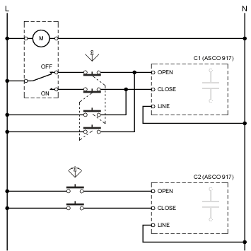
Here's a pic of the schematic. Hope someone can help because i'm lost one where to bring my power first and with what to leave from one item to the next.
- do I need both if any neutrals in the time clock and relays?
- where do I start?

photo.jpg
 

infinity

Moderator
Staff member
Location
New Jersey
Occupation
Journeyman Electrician
Looks like you have two ASCO 917 latching contractors. The one on the bottom has incorrect control circuit wring as there is no control voltage. Is the time clock momentary contact?
 

Oohitec

Member
Location
NYC
Yeah I do have two ASCO relays and all the voltage is 277V. I'm not sure if the clock is momentary but the way they intend it to operate is for the clock to override everything in case they forget to shut the lights manually.
 

Smart $

Esteemed Member
Location
Ohio
I'm pretty confused with a lighting system that i'm working on. I could really use some step by step clarification on the schematic.

I have:
- Two master keyed switches on two separate circuits with separate neutrals (277V)
- one master switch has (5) sub toggle switches controlling m1-m5
- the other master goes directly through the relay controlling lights (e) and (j)
- all of these lights need a Tork TZ-222L time clock and go through an ASCO #917 relay
- the returns from the (5) toggle switches need to go through an additional ASCO #917 relay
Well for one, your description don't match the schematic... but the schematic is incomplete. We can get into this later as more important issues must be remedied first.

Here's a pic of the schematic. Hope someone can help because i'm lost one where to bring my power first and with what to leave from one item to the next.
- do I need both if any neutrals in the time clock and relays?
- where do I start?
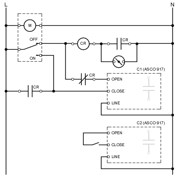
Yes, you need a control-circuit neutral run to the time clock. I looked up the model and it is a motorized unit, not that it matters regarding the neutral... it would need one even if it were digital. Here's a redraw of the control circuit (in ladder diagram form):

LightingContactorControl1.gif


NOTE: C2 will not operate as drawn.

...the way they intend it to operate is for the clock to override everything in case they forget to shut the lights manually.
It will not function as expected.

Considering just the time clock, key switch, CR, and C1 as controlling the lights, the time clock switching to ON will always signal C1 to CLOSE and turn on the lights.

When the time clock switches to OFF, and the key switch is OPEN. C1 opens... lights go OFF.

When the time clock switches to OFF and the key switch is CLOSED. C1 opens... but only momentarily, because CR energizes, changes the state of its contacts, and the N.O, contact to lower left in diagram CLOSES, energizing C1 "CLOSE" terminal... result: lights blink OFF momentarily and then back ON.

However, using convoluted thinking, labeling the key switch "closed" as OVERRIDE ON and "open" as AUTOMATIC, it will function as such... but in the OVERIDE ON position, the time clock will not turn the lights OFF.

I believe the preceding account to be correct. Will someone please check both my diagram and logic for correctness...
 

fmtjfw

Senior Member
with the right switch

with the right switch

The system will work as desired (for the first contactor) if the key switch is a momentary-on device. It would have a spring return to off when released. We use spdt momentary key switches to control basketball backboard raise/lower motors in gyms.


Wait, I need to reanalyze the diagram.
 
Last edited:

fmtjfw

Senior Member
The system will work as desired (for the first contactor) if the key switch is a momentary-on device. It would have a spring return to off when released. We use spdt momentary key switches to control basketball backboard raise/lower motors in gyms.


Wait, I need to reanalyze the diagram.

The specification makes no sense:
If the clock is on then operating the key switch makes no difference to the contactor
If the clock is off then operating the key switch closes the contactor
If the clock is off the key switch can seal in CR until the clock goes on

The circuit seems to allow an override on until next clock on, but no way to clear an override manually.

You need to get them to reformulate the specifications:roll:
 

Oohitec

Member
Location
NYC
I couldn't find an operations manual on the website, but the parts pdf shows the typical set-screw cam operators. To me, that suggests ON/OFF operation, not momentary.

http://www.nsiindustries.com/Repository/Files/T900L_TW_TZSeries_Parts.pdf

The TZ222L indicates Astronomic with bypass switches

http://www.nsiindustries.com/Repository/Files/eTIMESWITCHGUIDE.pdf

The entire diagram seems more complicated than it should be. I'm going to ask the engineer for some clarification. This Job's deadline is in 5 days; so I don't have much time.
 

hillbilly1

Senior Member
Location
North Georgia mountains
Occupation
Owner/electrical contractor
The diagram is totally fubar'd, I know what the engineer is trying to do, but none of that is going to work. The time clock needs to drive "CR" with a single N/O contact, the auxiliary contact from "CR" needs to parrallel this contact along with the momentary key switch contact. In turn "CR" drives the latching contactor with a common set of "N/O" and "N/C" contacts. Don't know why he is driving the "CR" relay with the neutral, but it will not work anyway as drawn. As others have said the second contactor will not work at all as drawn either. I will try to draw a diagram with the correct wiring if I can get it small enough to post.
 

Smart $

Esteemed Member
Location
Ohio
The TZ222L indicates Astronomic with bypass switches

http://www.nsiindustries.com/Repository/Files/eTIMESWITCHGUIDE.pdf

The entire diagram seems more complicated than it should be. I'm going to ask the engineer for some clarification. This Job's deadline is in 5 days; so I don't have much time.
The bypass switches help... but if CR is energized by key switch when TC is OFF, which will CLOSE C1, you'd have to turn TC bypass ON, then bypass OFF, to OPEN C1 (provided key switch is momentary).
 

hillbilly1

Senior Member
Location
North Georgia mountains
Occupation
Owner/electrical contractor
It still doesn't show up on my MS product, but any how, as others have said, the key switch will have to be momentary contact if it is to work as the engineer wants. It would still work with a maintained switch if wired by my diagram, but the time clock would be unable to reset the lighting with the key on. A standard time clock would be used. Unless it is a weird cheap latching contactor, it should already have clearing contacts built in, or a factory two wire module could be installed. No major changes in the diagram, just deletion of some wires. I did not show all of the neutrals in the diagram as where they go is pretty evident.
 

Smart $

Esteemed Member
Location
Ohio
It still doesn't show up on my MS product, but any how, as others have said, the key switch will have to be momentary contact if it is to work as the engineer wants. It would still work with a maintained switch if wired by my diagram, but the time clock would be unable to reset the lighting with the key on. A standard time clock would be used. Unless it is a weird cheap latching contactor, it should already have clearing contacts built in, or a factory two wire module could be installed. No major changes in the diagram, just deletion of some wires. I did not show all of the neutrals in the diagram as where they go is pretty evident.
I found a "more" relevant publication for the time clock...

http://www.nsiindustries.com/Repository/Files/2011.eTORKCatalog_25.pdf

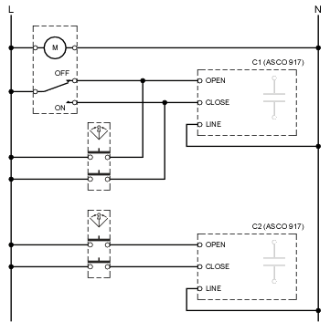
With bypass switches in the time clock, I can only guess that the key switch(es) are so nobody has to or can get into the time clock. But really there isn't even a need for the CR relay. Just get a 3-position keyed selector switch with center return and two (2) N.O. blocks. Run a hot to one side of each block, then take each other side to OPEN and CLOSE, respectively, on the contactors. IF I'm feeling generous, I'll draw it up...
 

Smart $

Esteemed Member
Location
Ohio
After giving this arrangement some thought, the paralleled momentary (spring return) key switch wont work with C1... because the time clock output is constant. As soon as the contactor is triggered to the opposite of its current state, the the C1 internal clearing contacts flop and the output of the time clock seizes control. Will have to give it some more thought, but it may work using a non-momentary (i.e. non-spring return) operator and dual N.O/N.C blocks. The N.C. blocks would be used to isolate the time clock output...
 
Status
Not open for further replies.
Top