MWBC= more heat or Less heat?

Status
Not open for further replies.
I would think they would be the same, as they are part of the same circuit. I don't see how you could have +120v on one part of a circuit, and -120v on another.

Acutally, your right, on a simple circuit like we've been discussing they would be the same. When A leg is -120V in relation to neutral, B leg will be +120V in relation to neutral (single-phase).
 
Acutally, your right, on a simple circuit like we've been discussing they would be the same. When A leg is -120V in relation to neutral, B leg will be +120V in relation to neutral (single-phase).

Current flow would be opposite in relationship to the neutral, but I can't see how voltage would be on opposite sides of zero.
 
Acutally, your right, on a simple circuit like we've been discussing they would be the same. When A leg is -120V in relation to neutral, B leg will be +120V in relation to neutral (single-phase).
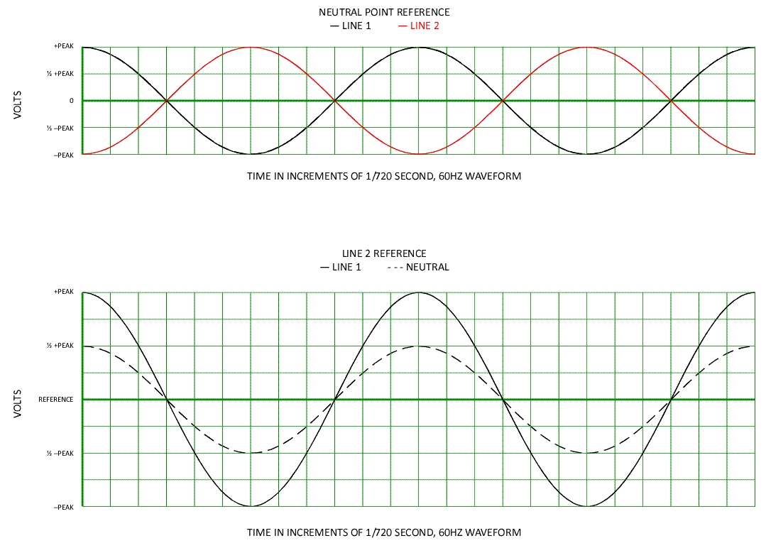
It's dependent upon the measurement's reference point in the circuit.


Split-PhaseVoltageWaveform.gif
 
Of course you're right, but as far as I knew, we have been referencing neutral this whole thread.
Yes, but when you reference the neutral point, the current appears to go in opposite directions in a balanced 3-wire circuit... which is not accurate. It is the same current measured in the opposite polarity.
 
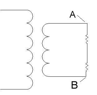
So how can Point A on this diagram be +120v while Point B is -120v?

singlephaseloads.jpg
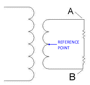
Because the reference point is in the center and you are measuring both directions from that reference point. This assumes you keep the same lead of the measuring point at the center for both measurements. Both voltages are part of the same sine wave and they cannot really be out of phase with each other, however the hook-up with a center tap makes them work like they are. Just exactly like measuring the voltage, while keeping one lead connected to the center.
 
So how can Point A on this diagram be +120v while Point B is -120v?
Your diagram leaves several parameters having to be assumed. For one, I believe you intentionally left out the center-tap on the secondary winding, the connection between loads, and the value of the loads. The following diagam is one scenario, and the 120V plus and minus can be measured from the center-tap, assuming a 120/240 1? 3W secondary.

Split-Phase.gif
 
This makes sense. Now can anybody explain the neutral-180 degree voodoo Dennis mentioned.
Picture the two batteries in series with the metal tab between them. From the tab's point of view, the batteries are "out of phase" by 180 degrees. It sees one battery's + and the other battery's - terminal.

From a 3v bulb's point of view, the batteries are in phase. They're additive, which is how two 1.5v batteries produce 3v. If one battery was flipped, there would be 0v output, becuase the connection would be subtractive.

Added: The two 1.5v bulbs don't care about either battery's polarity, and both would light up regardless. But, the 3v bulb would only light up with the relative polarities correct; which is to say "in phase."
 
Last edited:
But back to the subject....... if leg A and leg B of a single phase circuit are on a MWBC, they are part of the same circuit. I don't see how you can have 120volts above zero on one part, and 120volts below zero on another.
Actually, that is accurate. Like the batteries in series, look at it from the neutral's point of view. One line is + while the other is -. That's how they add to 240v.
 
Your diagram leaves several parameters having to be assumed. For one, I believe you intentionally left out the center-tap on the secondary winding, the connection between loads, and the value of the loads. The following diagam is one scenario, and the 120V plus and minus can be measured from the center-tap, assuming a 120/240 1? 3W secondary.

Split-Phase.gif


I still can't see electrons flowing one direction at point A (let's say, straight down to Point B) while at the same time, electons are flowing the other direction at Point B (travelling towards Point A).
 
So how can Point A on this diagram be +120v while Point B is -120v?

singlephaseloads.jpg
If that's a 240v secondary, then you do get the +/- 120v (from the not-shown center tap), which add to 240v.

If that's a 120v secondary, you'd get +/- 60v, which would add to 120v.
 
I still can't see electrons flowing one direction at point A (let's say, straight down to Point B) while at the same time, electons are flowing the other direction at Point B (travelling towards Point A).
That's just it; they aren't. The electrons are moving from the top of the secondary, past point A and through the upper load, through the lower load, and past point B into the bottom of the secondary.

If a wire (the neutral) was connected between the center of the secondary and the center point between the loads, no current would flow on the neutral wire as long as the loads remained equal.

Each half of that clock-wise current in the large loop could just as easily be described as two small current loops, the upper half and the lower half. The neutral currents would cancel each other.

Remember that this current reverses twice per cycle, but for this discussion, we could be using batteries and DC. If the two small-loop currents become unequal, the neutral would carry the difference.
 
Last edited:
It looks like this thread may be slowing down so ..........


That's just it; they aren't. The electrons are moving from the top of the secondary, past point A and through the upper load, through the lower load, and past point B into the bottom of the secondary.

Do the electrons really move that far with AC? :grin:
 
It looks like this thread may be slowing down so ..........

Do the electrons really move that far with AC? :grin:
So, ya wanna get all technical on me, eh? All righty: Well, not one electron, but the effect. Electrons are actually rather slow.

I once read an individual electron can move something like 1 inch in an hour, or in 1000 years, or something like that.
 
Status
Not open for further replies.
Top