MWBC= more heat or Less heat?

Status
Not open for further replies.
I still can't see electrons flowing one direction at point A (let's say, straight down to Point B) while at the same time, electons are flowing the other direction at Point B (travelling towards Point A).
They are flowing in the same direction looking from the outside, but looking from the neutral and looking toward point A you will see the electrons coming at you and turning and looking at point B you will see they going away from you.
 
I still can't see electrons flowing one direction at point A (let's say, straight down to Point B) while at the same time, electons are flowing the other direction at Point B (travelling towards Point A).
Current does not, cannot travel in two directions simultaneously through a single wire... only one direction at a time.

What I'm wondering is how did we got from talking about measuring +120V and ?120V to talking about current flow? :-?
 
Current does not, cannot travel in two directions simultaneously through a single wire... only one direction at a time.

So, given that, and if voltage and current flow together, then how can current be restricted to flowing one direction at a time, but not voltage? The only way voltage can be opposite is if the electrons are flowing the opposite direction.

What I'm wondering is how did we got from talking about measuring +120V and ?120V to talking about current flow? :-?


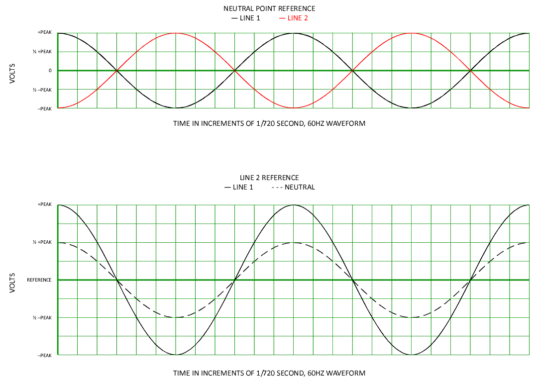
Didn't you post this image about voltage?
Split-PhaseVoltageWaveform.gif
 
Current does not, cannot travel in two directions simultaneously through a single wire... only one direction at a time.

What I'm wondering is how did we got from talking about measuring +120V and –120V to talking about current flow? :-?

I think I did it. I can see a 240V series circut with two loads. I can't see the MWBC circut.

I can wire it, I know what to do when I'm working on it, I know how to blow up the drywallers radio when he's playing obnoxious drywaller music, now I want to understand it.
 
How about this as an example (ok let me exhale first:D)

I'm sure many of us have wired a simple step down transformer with a 120/240 secondary?

you have 4 leads.

X1-120 volt winding 1-X2
X3-120 volt winding 2-X4

If we took a snapshot measurement of 1/60th in time when X1 is positive, the following would be the polarities of the other connections in that same time frame.

X1 pos
X2 neg
X3 Pos
X4 neg

As you see 120 winding 1 is in exact phase with 120 winding 2

If this wasn't true then we could not parallel winding 1 together with winding 2 by connecting X1+ to X3+, and X2- to X4- for 120 volts out, but double the current.

but for 240 we connect X2- to X3+ with our center tap(neutral) and our lines are X1+ and X4-

Note the polarity by each connection, just like in Larry's battery system this allows it to be an additive circuit

Inhale whooooooosh:wink:
 
Note the polarity by each connection, just like in Larry's battery system this allows it to be an additive circuit
And, just like batteries, can be paralleled for twice the current at the same voltage.

Inhale whooooooosh:wink:
Heard from a dead blonde's misplaced headphones: " ... inhale ... exhale ... inhale ... exhale ... "
 
So, given that, and if voltage and current flow together, then how can current be restricted to flowing one direction at a time, but not voltage? The only way voltage can be opposite is if the electrons are flowing the opposite direction.
It's a matter of relativity to the point of reference. The physics of current is restricted to flowing in one direction, and the voltage potential is also locked into that same direction. However, this discussion is mixing two different aspects, that of the physics and the measurement thereof. You can measure voltage and current differently in sections of a circuit by simply changing the reference point and polarity of the measuring equipment. Yet the physics of voltage and current are bound to each other no matter which way you decide to measure it.

In a 3? phase circuit, it is possible to measure a positive voltage from one reference point to two test points and still have current flow between the two positive test points because they are at a different potential to each other. With respect to each other, one point is more positive and the other more negative, and this fact will determine which way the current flows.

Didn't you post this image about voltage?
Yes, but not as a reply to your post.
 
It's a matter of relativity to the point of reference. The physics of current is restricted to flowing in one direction, and the voltage potential is also locked into that same direction. However, this discussion is mixing two different aspects, that of the physics and the measurement thereof. You can measure voltage and current differently in sections of a circuit by simply changing the reference point and polarity of the measuring equipment. Yet the physics of voltage and current are bound to each other no matter which way you decide to measure it.

In a 3? phase circuit, it is possible to measure a positive voltage from one reference point to two test points and still have current flow between the two positive test points because they are at a different potential to each other. With respect to each other, one point is more positive and the other more negative, and this fact will determine which way the current flows.


Yes, but not as a reply to your post.

Similar subject----Why is it when a person connects LINE "A" directly to LINE "B" with a small wire , it instaneously melt down in dramatic arc flash fashion (we all have seen upfront and close) --HOWEVER- when the little wire is wrapped around a peice of steel 100 times the set-up goes huuummmmm and it is called a transformer or solenoid????? I've read many textbooks. What is your best analogy as to how/why electrons-current does this????
 
What is your best analogy as to how/why electrons-current does this????
Because the increased inductance, contributed to by both the conductor coiling and the steel core, presents enough impedance to limit the current.

The effectiveness of BX/AC sheath as an EGC was improved by the little bonding strip, which shorted the spiral's wrap and decreased its impedance.
 
Because the increased inductance, contributed to by both the conductor coiling and the steel core, presents enough impedance to limit the current.

The effectiveness of BX/AC sheath as an EGC was improved by the little bonding strip, which shorted the spiral's wrap and decreased its impedance.


THanks for the reply to a obtuse question...
OK That explainations sounds like a textbook answer.. My dense, thick as a brick, head would appreciate a analogy as to how EMF elctro-mechanical-force works???? I often try to compare the behavior of electricity to the behavior of pressurized air in a pipe -pressure(X) volume -is similar to- amperage(X)voltage.

I often explain the following analogy to mechanics.

A rupture near a high pressure tank is violent compared to a small leak in a 3/8 hose over 400ft away. -- can be comparable to-- A dead short near a big XFMER as to a spark-out on a 12 ga wire fed from 15 amp over 400ft away.


Can EMF behavior be compared to air pressure behavior??

For instance-a small balloon inside a larger balloon. Inflate the inner balloon and the larger balloon expands also??? or the reverse Increase pressure in the outer balloon and the inner balloon shrinks. Could this be a visual clue on how a simple XFMR works???

I think about these things when I have trouble sleeping, or is it the reverse, I have trouble sleeping when I think about these things????

I'm normal and everybody else has a problem, or is it the reverse, everybody else is normal and I'm the one with problems????


Come on guys. HOW does electricity WORK ???? What is your best answer that does NOT come from a textbook???

I CHALLENGE you to a reply !!!

DENNIS
 
HOW does electricity WORK ???? What is your best answer that does NOT come from a textbook???

I CHALLENGE you to a reply !!!
Sir, I accept your challenge! :grin: I can't explain everything first, so I'll start with how electricity flows through a conductor, using your favorite analogy, a pipe (sort of), but instead of air or water, marbles.

Imagine a garden hose filled from end to end with marbles. What happens if you force another one in one end? A marble pops out of the other end. Not the same marble, but a similar marble.


Electrons orbit the nuclei in layers (aka valence shells.) The first layer can contain one or two electrons; if the atom happens to have a third electron, it will be the start of the second layer (up to eight), etc.

If the outermost layer is filled, or nearly filled, the electrons are bound tightly to the atom, and cannot be easily bumped away by another electron. These materials are electrically insulative.

Materials that are electrically conductive happen to have only one (or sometimes two) electrons in the outermost layer, and these 'free electrons' are easily bumped away and replaced by another one.

Gold, silver, copper, aluminum, and most other metals all happen to have only one electron in their outermost layer (aka a valence shell), so that electron can easily be displaced by a 'rogue' from outside.

A new electron introduced into one end of a conductor takes the place of the free electron of the 'first' atom, which bumps into the free electron of the next atom, and so forth. There is one requirement:

The free electron from the 'last' electron must have a place to go, which is why an electric circuit must be a loop, to provide a pathway for what we often call current 'returning to the source.'


Now, back to pipe: imagine a closed loop of 1" pipe with a circulating pump in the loop. The 'current' of water will flow through the loop as fast as the pump can pump it. Let's add that speed heats the water.

Now, in order for anything useful to be done, we add a hydraulic motor halfway around the loop, to spin, say, a fan. The harder the fan is to spin, the harder the pump is to spin, so will need a longer handle.


Electrical analogy: The pump is a generator, the pipe is a conductor, the hydraulic motor is a load, the water pressure is the voltage, and the resultant flow (based on pressure and resistance) is the current.

If we decrease the diameter of the pipe (smaller wire gauge), friction (resistance) adds to the difficulty of moving the water; likewise, a larger pipe reduces the friction. We also have to move the load.


Wow! I expected this to be a short analogy. Oh, well. I think you get the idea. Let me know if this is either too basic or too complex.
 
Man, I hope you're going to let him exhale sometime soon... he's probably past dark blue and into shades of purple by now :grin:

Oh no, not HURK!! Wayne lives in Lake Co. IN where holding your breath for most of the summer is a practiced art form, designed to avoid breathing Chicago smog.
 
Last edited:
Oh no, not HURK!! Wayne lives in Lake Co. IN where holding your breath for most of the summer is a practiced art form, designed to avoid breathing Chicago smog.

Not that it makes much difference, I'm in porter Co. one more to the east, and between the smog off Chicago, and the Gary steel mills, yes it can be rather discomforting:mad: yet we are the ones who have to get our cars emission tested:mad: Go figure:rolleyes:

By the way, I grew up in Florida, so swimming and diving was a favorite of mine (till I moved up here Brrrrr) I used to be able to hold my breath a long time. some used to say I would have been a great congressman, as I could talk for a long time without taking a breath LOL:grin:

But then again I think Larrys post "96" got me beat
 
Last edited:
Status
Not open for further replies.
Top