Power factor and VA vs Watts

Status
Not open for further replies.
Your comment:

was about instantaneous power.
One Volt and one Ampere at the same instant is one Watt.
That is not a debatable point.
If it will help you respect me more, I won't debate it. Doesn't mean I agree with what you are saying though ;) You'll have to let me know where you stand on this :)

In the meantime, can you at least agree that in a reactive circuit there is energy which goes into the load, is stored temporarily, then returns from the load, and in intervals? ...and that energy is transferred in the form of electrical current? If yes to the immediately preceding question, does this action represent utilized energy (i.e. not the capacity or potential to do work, but actual work)?
 
Personally, I don't care if we call power vectors or scalars. I was just explaining why I think some authors use scalars, and then just write S=P+jQ. I think they are math purists.
Some authors are adamant they are scalars because some other authors define energy as a scalar physical quantity. IMO, its a matter of whether you confine your discipline to the teachings of those authors. Being an author does not make one an absolute authoritarian.

Engineers tend to be the other way. We don't care if we are mathmatically exact or not, as long as we get the write answer, we're happy:grin:
...and you practice what you preach in other realms, too :D
 
Information:


The magnitude of complex power is referred to as apparent power.


|S| = sqrt( (sqrt)P + (sqrt)Q )

Apparent power, like complex power is measured in volt ampere. The apparent power unit is volt-ampere

I've been following this for a bit but it sure seems like this should be more like

|S| = sqrt[ (P^2) + (Q^2) ]
 
...

No, I didn't forget. In the context I was speaking, S, P, Q are vectors.

...
...and what you refer to as context is what I meant when I used the terms "instantaneous domain" and "RMS domain" a while back. Yeah, I told you to forget I mentioned it... but it's back :cool:

When working with equations in the "RMS domain", the quantities are scalar. I need not say what they are in the instantaneous domain, for I believe anyone that can make sense of this discussion knows where I stand.
 
I have to add I disagree with the authors' implications in their figure (below)...
attachment.php

The authors state, "During the time interval corresponding to area "A", the source is delivering energy to the load,whereas during the time interval corresponding to area "B", a percentage of this amount of energy is being returned back to the source."

While their statement is not a complete fallacy, it erroneously implies that during the time interval corresponding to area "B" is the only time during which energy is being returned to the source. This implication is not true. At best, it is indicative only of some energy being returned to the source and is of the time interval of the leading half of energy being returned.

Referring to my latest chart below, my area "A" corresponds with the authors area "B". Pease note the overall hatched area with the line color cyan. The instantaneous magnitudes in this area are depicted by the "reactive power" waveform (dashed cyan). The time interval for both my areas "A" and "B" is the period which energy is being returned to the source, while the time interval corresponding to both my areas "C" and "D" is the period which energy is being stored by the load. There is only an instant between periods.

PFVAW5.gif
 
100415-1956 EST

Ham:

In the link you provided I have to disagree with the printed equation.

Make the phase angle 0, then the equation reduces to 1 + cos 2t. This wrong.

When you have a resistive load on a sine wave source, then at angle 0 (time 0) the voltage is 0 and so is its square, and therefore the instantaneous power is zero. Your equation says that it is 2*(V^2/R) which clearly is not. Intuitively and by the trig identity for sin^2 t it is 0. Maximum instantaneous power occurs at Pi/2 on the voltage curve, and it is back down to 0 at the voltage zero crossing.

Plot the voltage starting at sin 0. Then plot your 1 + cos 2t on the voltage plot.

Why do some of you want to start your plots at the voltage peak instead of the zero crossing? I have always started plots at the sin wave positive slope zero crossing unless there a special reason to start at some other angle.

.
 
...

Why do some of you want to start your plots at the voltage peak instead of the zero crossing? I have always started plots at the sin wave positive slope zero crossing unless there a special reason to start at some other angle.
Q: If we have a voltage vector of 120Vrms@0?, what is the instantaneous voltage at t=0?

A: 169.7V.

Hopefully this Q&A also answers your question.
 
Last edited:
...In the link you provided I have to disagree with the printed equation.

Make the phase angle 0, then the equation reduces to 1 + cos 2t. This wrong.

When you have a resistive load on a sine wave source, then at angle 0 (time 0) the voltage is 0 and so is its square, and therefore the instantaneous power is zero. Your equation says that it is 2*(V^2/R) which clearly is not. Intuitively and by the trig identity for sin^2 t it is 0. Maximum instantaneous power occurs at Pi/2 on the voltage curve, and it is back down to 0 at the voltage zero crossing.

Plot the voltage starting at sin 0. Then plot your 1 + cos 2t on the voltage plot.

...
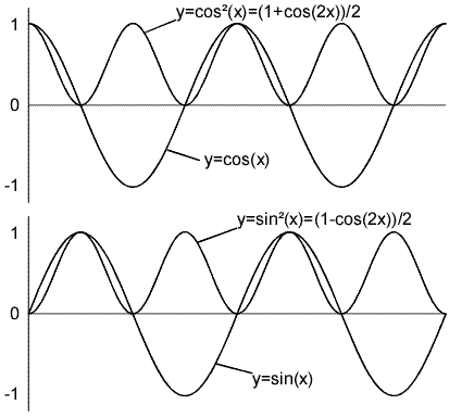
Taking the preceding Q&A into account, 2 cos?(x) = 1 + cos(2x).

Your are trying to apply the "counter-identity" where it doesn't apply.
 
Last edited:
100415-2056 EST

Smart $:

You could choose to associate phasors with any arbitrarily defined reference point on the sine wave. No reason it has to be the peak. it just has to be a defined relative position.

When one is simply working with the time varying arbitrary signal of arbitrary periodic waveform it is usually much more useful to work with a zero crossing reference.

An experiment you can run to realize that if you are correlating instantaneous power with instantaneous voltage that the correlation is per 1 - cos 2t :

Get a fine wire resistance with a fast thermal time constant, use a small pilot light bulb. Connect this to a low frequency oscillator, like 0.1 Hz. Plot voltage on a scope and synchronize to its zero crossing. On a second channel with the same time base sweep plot wire temperature. A photo cell can do this for the pilot lamp. The lamp brightness is minimum when the voltage passes the zero crossing, and maximum at the voltage peak, and back down to 0 at the next voltage zero crossing.

.
 
100415-1956 EST

Why do some of you want to start your plots at the voltage peak instead of the zero crossing? I have always started plots at the sin wave positive slope zero crossing unless there a special reason to start at some other angle.

.

We're back to the sine vs. cosine argument. I think its kind of like asking why some of us use electron flow, and some use conventional current.

From my experience:

Engineering classes tend to use conventional current flow and cosine waves.

Technical classes and 2 year college programs tend to use electron flow and sine waves.

Smart$ and Gar: In many textbooks 170 @ 0 deg is shorthand for 170 sin t, and the waveform would be 0 at t=0. In most engineering textbooks, 170 @ 0 is shorthand for 170 cos t.


Steve
 
100415-2056 EST

Smart $:

You could choose to associate phasors with any arbitrarily defined reference point on the sine wave. No reason it has to be the peak. it just has to be a defined relative position.
This I realize. I'm just pointing out the generally accepted convention. Anyone reading my posts should be able to tell I can change from one convention to another on a whim :D:D:D

When one is simply working with the time varying arbitrary signal of arbitrary periodic waveform it is usually much more useful to work with a zero crossing reference.

An experiment you can run to realize that if you are correlating instantaneous power with instantaneous voltage that the correlation is per 1 - cos 2t :

Get a fine wire resistance with a fast thermal time constant, use a small pilot light bulb. Connect this to a low frequency oscillator, like 0.1 Hz. Plot voltage on a scope and synchronize to its zero crossing. On a second channel with the same time base sweep plot wire temperature. A photo cell can do this for the pilot lamp. The lamp brightness is minimum when the voltage passes the zero crossing, and maximum at the voltage peak, and back down to 0 at the next voltage zero crossing.
...and just what do you think (1 + cos 2t)/2 looks like? Isn't it just the same waveform as (1 - cos 2t)/2 inverted about itself? It does correlate with voltage calculated as a cosine function.

PS: I don't know which equation it is that you reduced to 1 + cos 2t.
 
100415-2240 EST

Smart $:

Unless you had Stout's course (Melville B. Stout, Professor of Electrical Engineering, University of Michigan) and used his book on Analysis of A-C Circuits you probably can not find this book. On page 13 equation (21) is clearly written with the equation for instantaneous power using the - sign. This is clearly an engineering perspective and not something else. Has nothing to do with direction of current flow being holes or electrons.

If you are to synchronize what is happening between instantaneous power and the sine wave voltage, then you must use the - sign.

Go back to the experiment I described in post 233. There is no way you can have maximum power occur when the voltage across the resistive load is at 0 V.

This has nothing to do with whether you want to call the voltage waveform a sine or cosine shape. With a sinusoidal waveform when the voltage is zero the resistive load power is 0. With a triangular waveform the same statement holds.

The Stout book has a 1952 copyright date and was Distributed by Ulrich's Book Store. The only library referenced by Google was the University of Michigan Engineering Library. Does not appear to be scanned by Google as yet.

.
 
If it will help you respect me more, I won't debate it.
Doesn't mean I agree with what you are saying though ;) You'll have to let me know where you stand on this :)
There is no if.
One Volt and one Ampere at the same instant is one Watt.
That's where I stand. :)

In the meantime, can you at least agree that in a reactive circuit there is energy which goes into the load, is stored temporarily, then returns from the load, and in intervals?
Loosely, yes. It is dynamic and flowing one direction or the other at a given rate at a given point in time. The diagram I put in post #141 indicates direction of flow.

...and that energy is transferred in the form of electrical current?
Not so. Energy has three terms in this context. Voltage, current, and time.
One Volt times one Amp times one second is one Joule. The Joule is the measurement of energy.
 
100415-2240 EST

Smart $:

Unless you had Stout's course (Melville B. Stout, Professor of Electrical Engineering, University of Michigan) and used his book on Analysis of A-C Circuits you probably can not find this book. On page 13 equation (21) is clearly written with the equation for instantaneous power using the - sign. This is clearly an engineering perspective and not something else. Has nothing to do with direction of current flow being holes or electrons.

If you are to synchronize what is happening between instantaneous power and the sine wave voltage, then you must use the - sign.

Go back to the experiment I described in post 233. There is no way you can have maximum power occur when the voltage across the resistive load is at 0 V.

This has nothing to do with whether you want to call the voltage waveform a sine or cosine shape. With a sinusoidal waveform when the voltage is zero the resistive load power is 0. With a triangular waveform the same statement holds.

The Stout book has a 1952 copyright date and was Distributed by Ulrich's Book Store. The only library referenced by Google was the University of Michigan Engineering Library. Does not appear to be scanned by Google as yet.

.
As I stated earlier, being an author does not make that person an absolute authoritarian.

Aside from that. I do not see where you have a problem...

sincosfunctionssquared.gif
 
Smart $ said:
If it will help you respect me more, I won't debate it. Doesn't mean I agree with what you are saying though ;) You'll have to let me know where you stand on this :)
There is no if.
One Volt and one Ampere at the same instant is one Watt.
That's where I stand. :)
Okay... I'll not debate the matter with you on the condition you not debate it with me either.
 
100415-1956 EST

Ham:
In the link you provided I have to disagree with the printed equation.
Make the phase angle 0, then the equation reduces to 1 + cos 2t. This wrong.
.

Using the attached two photos lets proof it where
p = P + Pcos2wt comes from .

p = vi --------1

This is instantaneous power is measured in watts when the

voltage is in volts and the vurrent is in ampere.

v = Vm cos(wt + 0v) ------2
i = Im cos(wt + 0i) ------3

0v voltage phase angle and 0i is current phase angle.

We are operating in the sinusoidal steady state, so we may

choose any convenient reference for zer time. Engineers

designing system that transfer large blocks of power have found

it convenient to use a zer time corresponding to the instant the

current is passing through a passitive maximum. This reference

system requies a shif of both the voltage and current by (0i)

thus eqs 2 and 3

v = Vm cos(wt + 0v - 0i),--------4
i = Im coswt.------------5

when we substitute Eqs 4 and 5 into Eq 1, the expression for the

instantaneous power becomes

p = Vm*Im cos(wt + 0v - 0i) coswt.----------6

Now by simply applying a couple trigonometric identities, we can

put Eq. 6 into a much more informative form.

we know this

cosx*cosB = 1*cos(x - B)/2 + 1*cos(x + B)/2

to expand equation 6 letting x = wt + 0v - 0i and B = wt gives

p = Vm*Im*cos(0v - 0i)/2 + Vm*Im*cos(2wt + 0v - 0i)/2 ----7

we know that
cos(x+B) = cosxcosB - sinxsinB

now we will expand the second term on the right hand side Eq. 7

which gives.

p = Vm*Im*cos(0v-0i)/2 + Vm*Im cos(0v - 0i)cos2wt/2 -

Vm*Im*sin(0v - 0i)sin2wt/2. ---------8

now see the attached graph file too.

graph depicts a representative relationship among v,i,and based

on the assumptions 0v=60 degre and 0i =0. You can see that the

frequencey of the instantaneous power is twice the frequency of

the voltage or current. this observation also follows directly

from the second two terms on the right hand side of Eq 8.

Therefore, the instantaneous power goes through two complete

cycles for every cycle of either the voltage or the curren. Also

note that the instantaneous power may be negative for a portion

of each cycle even if the network between the terminals is

passive. In a completely passive network, negative power implies

that energy stored in the inductors or capacitors is now being

extracted.

Now

We begin by noting that Eq 8 has threee terms which we can

rewrite as follows.

p = P + P*cos2wt - Q*sin2wt. -----------------9

P = Vm*Im*cos(0v - 0i)/2 -----------------10

Q = Vm*Im*sin(0v - 0i)/2 -----------------11

P is called the average power and Q is called the reactive

power.


If the circuit between the terminals is purely resistive the

voltage and current are in phase which means 0v = 0i. Equation 9

then reduces to

p = P + Pcos2wt.

This the method of how to prove the p = P + Pcos2wt.

Now if you are saying it is a wrong formula please proof it step by step and we all learn it.
 
Status
Not open for further replies.
Top